K-Jetronic fuel injection system
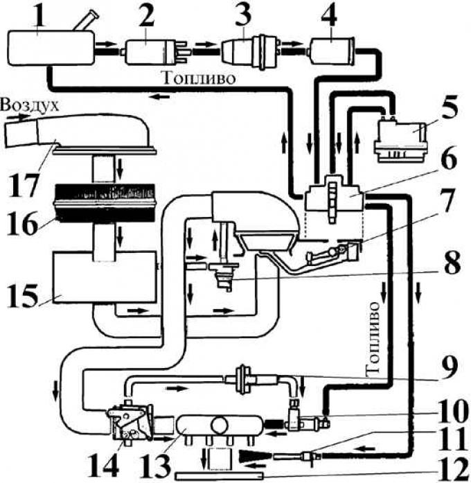
1 – fuel tank; 2 – fuel pump; 3 – pressure accumulator; 4 – fuel filter; 5 – temperature regulator; 6 – fuel distributor-metering device; 7 – air flow meter; 8 – shut-off valve; 9 – additional air supply; 10 – starting nozzle; 11 – nozzle; 12 – intake manifold; 13 – air chamber; 14 – throttle valve; 15 – air intake chamber; 16 – air filter; 17 – air intake
The Bosch K-Jetronic system is a mechanical fuel injection system with continuous fuel injection into the intake manifold in front of the intake valves.
Fuel under pressure developed by the fuel pump is supplied through a pressure accumulator and a fuel filter.
The air flow is regulated by the throttle valve depending on the position of the accelerator pedal. The amount of air entering the engine cylinders through the flow meter is the main value that controls the mixture formation process.
The fuel quantity distributor delivers a certain amount of fuel according to the measured amount of air to the corresponding injectors.
Sensors located on the engine provide precise fuel dosage in all engine operating modes at any ambient temperatures.
To save fuel, there is a system that shuts off the fuel supply in engine braking mode.
Operating principle of a vane roller pump
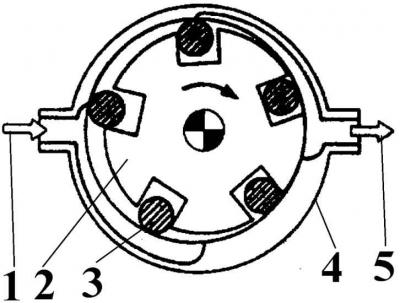
1 – fuel supply from the fuel tank; 2 – rotor; 3 – roller; 4 – pump body; 5 – fuel outlet under pressure
Electric fuel pump
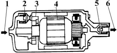
1 – fuel supply from the fuel tank; 2 – pressure reducing valve; 3 – vane roller pump; 4 – electric motor; 5 – check valve; 6 – fuel outlet under pressure
An electric fuel pump with a pressure reducing valve is installed near the fuel tank.
Pressure accumulator
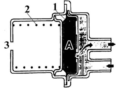
A – accumulated volume of fuel; 1 – diaphragm; 2 – spring; 3 – hole
The pressure accumulator reduces fuel pulsations created by the fuel pump and maintains pressure in the fuel line after the engine is turned off.
Fuel lines connected to the fuel distributor
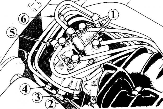
1 – to the injectors; 2 – to the start valve; 3 – return line; 4 – to the thermostat; 5 – fuel supply line; 6 – to the thermostat
The fuel filter consists of two paper filter elements that perfectly clean the fuel supplied to the injectors.
The fuel distributor controls the amount and uniformity of distribution of fuel entering the engine cylinders.
Air flow meter
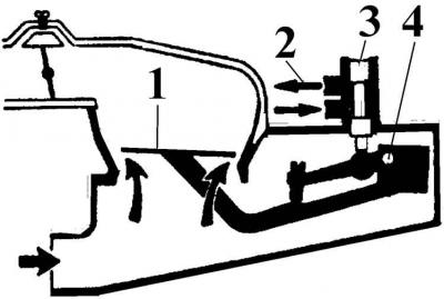
1 – pressure plate of the flow meter; 2 – distribution plunger; 3 – axis; 4 – direction of fuel flows
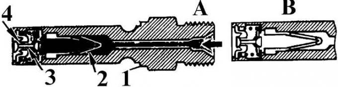
Control plunger
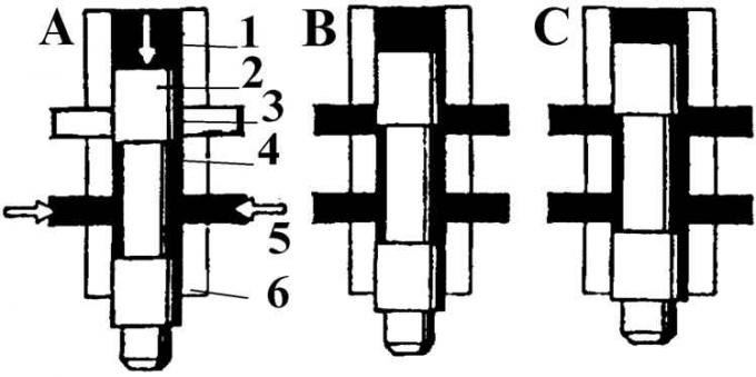
A - state of rest; B – partial load; C – full load; 1 – control pressure; 2 – control plunger; 3 – control edge; 4 – control edge; 5 – fuel supply; 6 – holder
The control unit includes a flow meter plate and a control plunger. In idle mode, the air flow lifts the pressure plate of the flow meter, which in turn moves the control plunger up, which passes fuel to the injectors. As the engine speed increases, the air flow increases, causing the control plunger to move up accordingly, which in turn changes the amount of fuel entering the injectors
Attention! Near each connector of the fuel pipe that supplies fuel to the injectors, on the distributor head there are special 4 screws of the initial installation, which are not adjustment screws and cannot be rotated.
Throttle valve
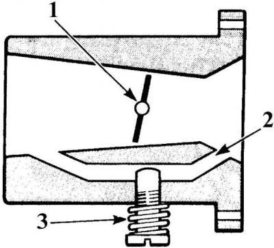
1 – throttle valve; 2 – air bypass channel; 3 – idle speed adjustment screw
The throttle valve is installed in the main air duct and is driven by the accelerator cable. When installed at the factory, the throttle valve drive mechanism is adjusted so that in the initial state the valve is partially open to prevent it from jamming in the fully closed position. Adjustment of the throttle valve during operation is not allowed. Idle speed adjustment is performed by a screw, which, depending on its position, to a greater or lesser extent restricts the air flow passing through the bypass air channel located in the throttle valve body.
Fuel injector
A – the nozzle is open; B – the nozzle is closed; 1 – nozzle body; 2 – filter; 3 – needle valve; 4 – valve seat
The injectors are installed in the intake manifold and open at a pressure of 3.5 bar. They atomize the fuel by oscillating the needle valve and inject it continuously into the intake manifold in front of the intake valve of each cylinder. After the engine stops, the pressure in the fuel system drops and the injectors close at a pressure below 3.5 bar.
The thermostat is located on the intake manifold and consists of two springs, a bimetallic plate and a control injection valve. The regulator controls the fuel supply to the control line, which regulates the pressure drops when the control plunger moves. The compression of the springs is regulated by a bimetallic plate, the amount of decompression of which depends on the engine temperature.
The auxiliary metering device is located on the intake manifold and consists of a rotating plate, a bimetallic plate and a heating element. This device supplies an additional amount of fuel-air mixture when the engine is idling at low air temperatures.
Starting nozzle in working position
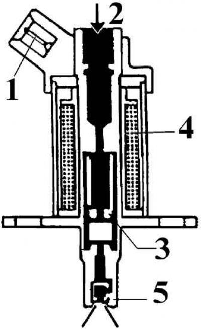
1 – electrical connector; 2 – fuel supply through the fuel filter; 3 – valve; 4 – winding; 5 – centrifugal atomizer
The starting injector with electrical control and a starting mode switch is designed to supply fuel to the air chamber during cold engine starting. Since July 1988, an improved starting injector has been installed.
The fuel pump protection unit is located under the dashboard on the driver's side and is purple in color. The purpose of the unit is to disconnect the power supply to the fuel pump in the event of a sudden engine stop.
Shut-off valve
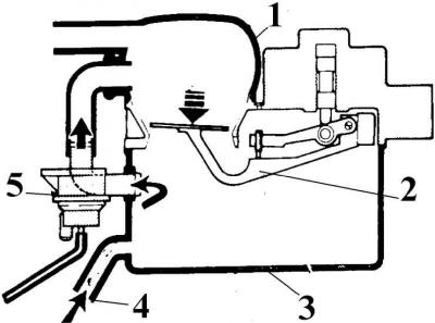
1 – suction air line; 2 – sensor plate; 3 – air filter housing; 4 – air channel; 5 – open shut-off valve
The shut-off valve serves to save fuel when warming up the engine and in certain driving modes of the vehicle.