Contents: Accelerator pump ↳ Carburetor vacuum device ↳ The device "Automat" ↳ Starting device ↳ Adjusting the engine idle speed ↳ Adjusting the "fast" idle speed ↳
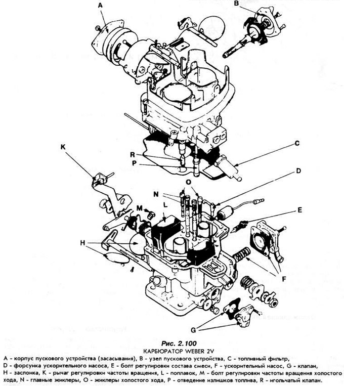
The 1.1 engine is equipped with a Weber 2V carburetor (Fig. 2.100). The carburetor has a mechanical accelerator pump and a vacuum-controlled mixture enrichment device at full engine load.
Accelerator pump
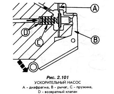
The accelerator pump supplies the engine with an additional portion of fuel during a sharp increase in vacuum (in the case of a rapid pressing of the gas pedal to the stop). The pump device is shown in Fig. 2.101.
Carburetor vacuum device
This device serves to slow down the closing of the valve when the gas pedal is released quickly. Due to the action of the vacuum device, combustion in the engine under the described conditions proceeds relatively calmly when an additional portion of fuel is supplied. Slowing down the closing of the valve is also used to limit the release of harmful substances into the exhaust gases. Fig. 2.102 shows a diagram of the vacuum device.
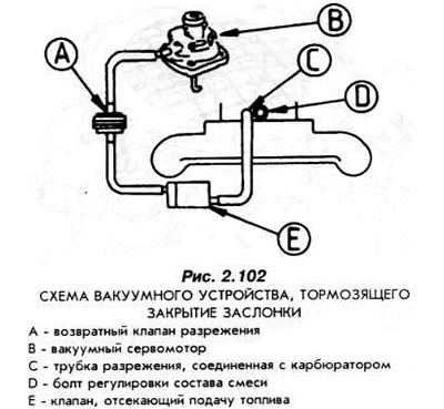
The device contains a check valve, which is affected by the vacuum created in the intake manifold during engine operation. If the pressure on the gas pedal is released, the above-mentioned check valve will maintain the vacuum for some time, which will increase the time it remains open. As the vacuum decreases, the engine smoothly switches to idle speed.
The device "Automat"
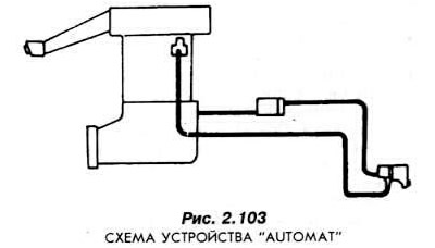
In cars with an automatic transmission, the "Automat" device acts as a speed compensator during transmission operation in the "R", "D" and "L" ranges (Fig. 2.103). This means that if the automatic transmission is in one of the states "R" - reverse, "D" - forward movement, or "L" - movement in urban conditions, and the car stops with the engine running - an automatic vacuum regulation of the engine speed occurs, which should make spontaneous starting from a standstill impossible.
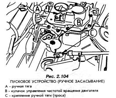
Starting device
The starting device is the so-called manual suction device. With its help, the air damper is closed. The vacuum increases and more fuel is supplied to the engine. The position of the damper can change within a certain range as a result of the action of the vacuum servomotor.
However, after the end of the starting phase, when the engine begins to operate steadily, the vacuum established in the suction tube opens the valve, which subsequently remains stationary in this position (Fig. 2.104).
Adjusting the engine idle speed
Warm up the engine until the radiator electric fan comes on.
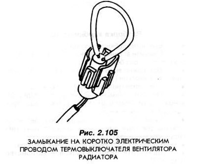
Short-circuit the fan's electrical wires so that it does not turn off. To do this, remove the thermal switch connector and short-circuit both contacts of the connector plug with a piece of electrical wire (Fig. 2.105).
Connect the tachometer and the device for measuring the CO content in the exhaust gases according to the instructions.
Remove the tube from the fast idle servo motor.
Increase the engine speed to 3000 rpm and let it run at this speed for 30 seconds.
After the engine idle speed has stabilized, take readings from the tachometer and exhaust gas CO meter.
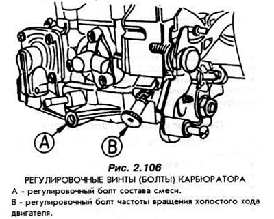
If the data obtained differs from the required ones, remove the seal from the mixture composition adjusting screw (bolt). To do this, remove the air filter. Connect the vacuum tube, install the air filter in place. The ventilation line of the main engine crankcase should also be connected to the filter.
Turn both screws shown in Fig. 2.106 while the engine is running and observe the readings of the tachometer and the device measuring the CO content in the exhaust gases. The adjustment should be completed after the tachometer and the device measuring the CO content show the required values. Install a new seal on the mixture adjustment screw.
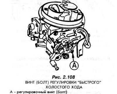
Adjusting the "fast" idle speed
Warm up the engine to the temperature at which the radiator fan turns on.
Short-circuit the fan motor electrical wires (Fig. 2.105).
Connect a tachometer and a device measuring the CO content in the exhaust gases. Compare the obtained values with the required data. If necessary, adjust the idle speed and mixture composition.
Remove the tube from the air filter (Fig. 2.107). Remove the multi-pin connector of the intake air temperature sensor.
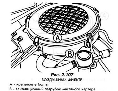
Disconnect the electrical wire from the shut-off valve and remove the air filter.
Pull the suction rod out fully and hold the starter valve in the fully open position. Start the engine and read the engine speed on the tachometer.
If necessary, adjust the rotation speed with screw (A) (Fig. 2.108).
Install the air filter. Reconnect all previously disconnected flexible tubes and electrical wires.