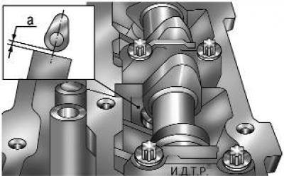
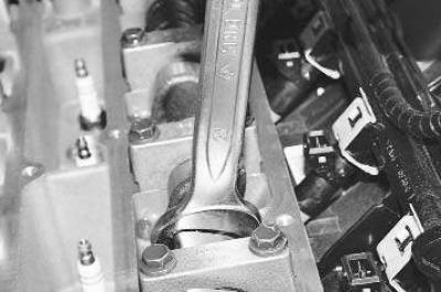
Fig. 5.9. Measuring the clearance in the valve drive: a – measured clearance
Gap a (Fig. 5.9) is measured with a feeler gauge on a cold engine (at a temperature of +20°C) between the camshaft cam (the cam should be directed upwards from the tappet) and the valve tappet. The nominal clearance for the intake valve is 0.17–0.23 mm, for the exhaust valve – 0.31–0.37 mm. Clearances are adjusted by selecting the thickness of the tappets. Sets of tappets of different thicknesses are supplied as spare parts.
With respect to the timing belt, the valves located on the right are exhaust valves, and those on the left are intake valves.
You will need: all the tools needed to remove the camshafts (see "Replacing camshafts"), as well as a set of flat feeler gauges.
1. Set the piston of the first cylinder to the TDC position of the compression stroke (see "Setting the piston of the first cylinder to the TDC position of the compression stroke").
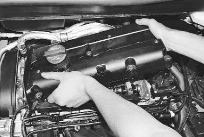
2. Remove the cylinder head cover (see "Replacing the cylinder head cover gasket").
3. Measure the clearance a (see Fig. 5.9) between the camshafts of both camshafts and the valve tappets using a feeler gauge. Record the measured clearances.
4. Rotate the crankshaft by the bolt securing its pulley each time by 180°, measure and record the valve clearances of the remaining cylinders. The order of operation of the cylinders is: 1–3–4–2. It is necessary to replace the tappets of those valves whose clearances differ from the nominal ones. After measuring all the clearances, set the piston of the 1st cylinder to the compression stroke position.
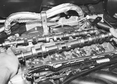
5. Remove the camshafts (see "Replacing camshafts").
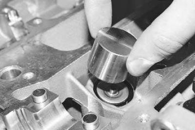
6. Remove the valve tappet that requires clearance adjustment from the cylinder head socket and record its thickness (it is indicated on its back side).
Note: The number stamped on the valve lifter is the lifter thickness. However, only three digits after the decimal point are stamped (e.g., "650" means the lifter thickness is 3.650 mm).
7. Calculate the thickness of the new tappet using the formula (all values in mm)
H = B+A–C, where
A — the value of the measured gap;
B — thickness of the old pusher;
C — nominal clearance;
H — thickness of the new pusher.
8. Install the new pusher into place.
9. Similarly, replace the tappets of all valves that require clearance adjustment.
10. Install the camshafts, but do not install the timing belt yet.
11. Turn the camshafts by the hexagons made on them and measure the resulting clearances with feeler gauges. If the clearances differ from the nominal values, repeat the adjustment (see paragraphs 6–8).
12. If all clearances correspond to the nominal values, turn the camshafts so that the cams of the valve drive of the 1st cylinder are installed as shown in Fig. 5.9.
13. Install the timing belt and all removed parts in the reverse order of removal.