Withdrawal
1. Remove the head covers and timing chains (paragraph 5, 9).
2. Temporarily screw the bolt into the end of the crankshaft so that the shaft can be rotated.
3. Remove MGR chains (paragraph 10).
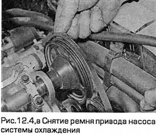
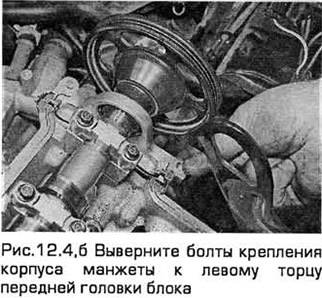
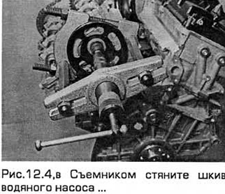
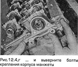
4. If you are removing the front head intake camshaft, pull the water pump drive belt tensioner toward the camshaft and remove the belt. Turn out bolts of fastening of the case of a cuff to the left end face of a forward head of the block. The coolant pump pulley can not be removed. But you can also remove the pulley, and then unscrew the bolts of the cuff housing (see fig. 12.4, a-g).
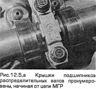
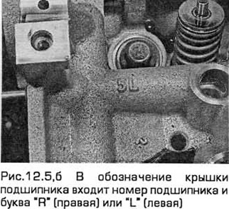
5. Check up labels on covers of bearings of camshafts. The designation of the bearing cover includes the bearing number and the letter «R» (right) or «L» (left) according to the block head. The rear head of the block is right, and the front is left (see fig. 12.5, a, b).
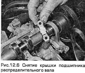
6. Alternately served the heads of the block, first remove the covers that perceive axial force - 1L and 5L or 1R and 5R. These covers can be removed before you loosen the rest of the bolts. Loosen the bolts and remove these covers (see fig. 12.6).
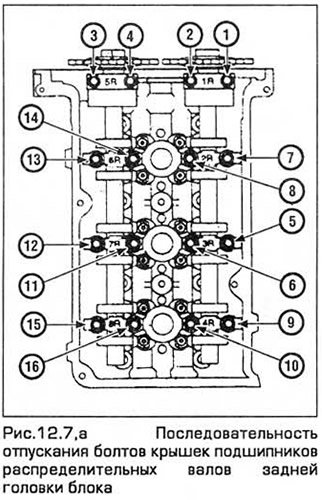
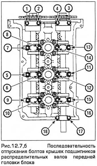
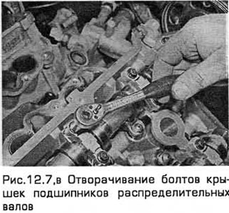
7. Consistently release (see fig. 12.7, a-c) bolts of other covers. Remove the covers, if necessary, by tapping them with a soft-faced hammer.
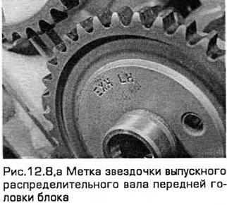
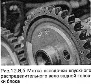
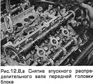
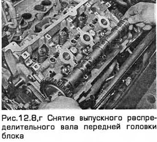
8. Remove the camshafts and store them so as not to mix up during installation (see fig. 12.8, a-g).
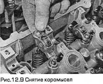
9. Consider the position of the rocker arms. Remove them and store them so as not to be mixed up during installation (see fig. 12.9).
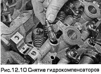
10. Remove hydraulic lifters and box with numbered sections (see fig. 12.10).
Inspection
11. After removing the camshafts and hydraulic lifters, inspect them for wear (scratches, pitting, etc.), as well as ovality. Replace defective components if necessary.
12. Measure the outer diameter of each hydraulic lifter. Measure the diameter at the top and bottom of the hydraulic lifter, and then repeat the measurements in the perpendicular direction. If any of the dimensions obtained is significantly different from the rest, then the compensator has a taper or ovality, and it must be replaced. If you have the necessary equipment, measure the inner diameter of the corresponding hole in the block head. Compare the obtained dimensions with the technical requirements. If the lifters or bores are excessively worn, you will need new lifters and/or a new cylinder head.
13. If the valve mechanism knocks, and especially when starting a cold engine, then a faulty hydraulic compensator is probably the cause of this. Only an experienced auto mechanic who knows such engines can determine by ear whether such noise is normal or whether one or more hydraulic lifters need to be replaced.
14. Inspect the camshaft cams for pinpoint wear marks, metal pitting or enveloping, and hot spots (tint colors). Inspect the hardened surface layer of each cam for chipping. If such signs are found, the camshaft must be replaced.
15. Examine necks of bearings of a camshaft and surfaces of bearings of a head of the block on presence of deterioration, in particular, point wear. If such signs are found, replace the block head.
16. With a micrometer, measure the diameters of the necks in several places. If the diameter of one of the necks is less than specified in the Specifications, replace the camshaft. If you have an internal micrometer, measure the holes formed by the block head and bearing caps.
17. Measure the axial clearance of the camshaft with a dial indicator. To do this, install it on the block head like this. so that the tip of the indicator rests on the end of the camshaft. Press the camshaft against the indicator, reset the indicator, and then press the camshaft away from the indicator and take readings. If the result obtained corresponds to the maximum backlash or exceeds it (see Technical Requirements), then it is necessary to replace the covers that perceive the axial force.
Installation
18. When servicing the front head of the block, generously lubricate the hydraulic lifters and the holes for them in the head of the block with oil. In the case of installing new hydraulic lifters, they must first be filled with oil. Carefully install the hydraulic lifters in the head of the block - in their places, with the corresponding side. Insert the hydraulic lifters into the holes without distortion.
19. Lubricate the rocker arms and install them in their places.
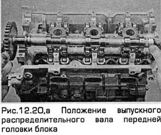
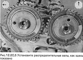
20. Copiously lubricate the camshaft bearing journals with oil. Install the camshafts in their places. The mark on the intake camshaft sprocket should be at the 9 o'clock position. The mark on the exhaust camshaft sprocket must be in the 12 o'clock position (see fig. 12.20, a, b).
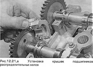
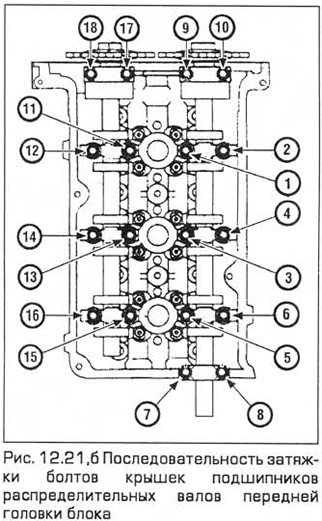
21. Establish covers of bearings of camshafts on the places. Insert the bolts and hand-tighten them sequentially. Then tighten the bolts to the required torque (see fig. 12.21, a, b).
22. Install the front head chain (paragraph 10).
23. When servicing the rear head of the block, generously lubricate the hydraulic lifters and the holes for them in the head of the block with oil. In the case of installing new hydraulic lifters, they must first be filled with oil. Carefully install the hydraulic lifters in the head of the block - in their places, with the corresponding side. Insert the hydraulic lifters into the holes without distortion.
24. Lubricate the rocker arms and install them in their places.
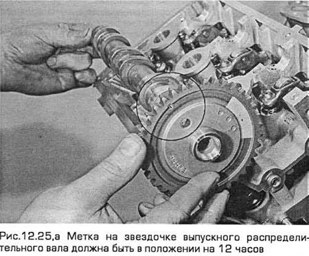
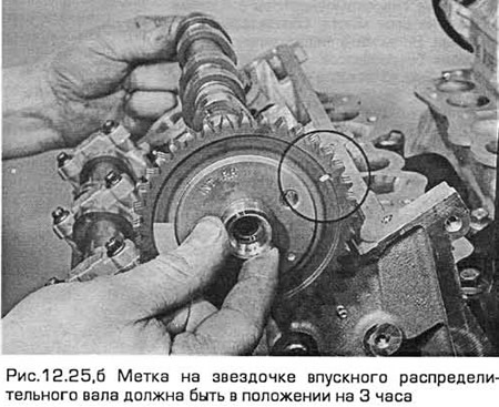
25. Copiously lubricate the camshaft bearing journals with oil. Install the camshafts in their places. The mark on the intake camshaft sprocket should be at the 3 o'clock position. The mark on the exhaust camshaft sprocket must be in the 12 o'clock position (see fig. 12.25, a, b).
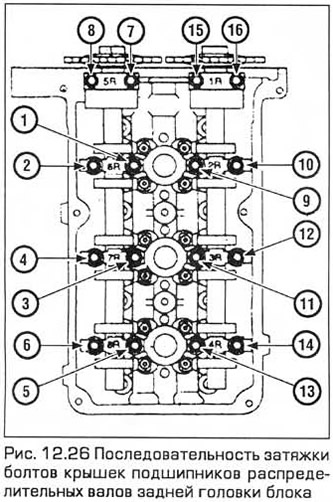
26. Establish covers of bearings of camshafts on the places. Insert the bolts and hand-tighten them sequentially. Then tighten the bolts to the required torque (see fig. 12.26).
27. Install the rear head chain (paragraph 10).
28. Install the covers of the MGR and block heads (paragraph 5, 9).
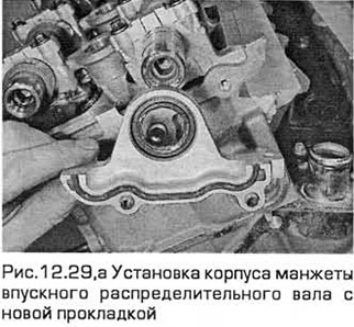
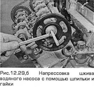
29. If the front head inlet camshaft seal housing was removed, install it on a new gasket. Then press the coolant pump pulley (see fig. 12.29, a, b).
Visitor comments