Removal
1. Turn the engine to the TDC position for cylinder No.1 (paragraph 4).
2. Remove the MGR cover (paragraph 9).
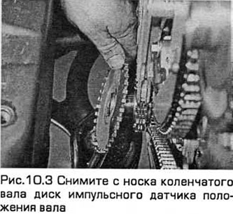
3. Remove the shaft position pulse sensor disk from the crankshaft, taking into account which side it is installed on. Mark the position of the sensor for its subsequent correct installation (see Fig. 10.3).
4. Temporarily screw the crankshaft pulley bolt into the end of the shaft so that it can be turned.
5. Note that the chain for each cylinder head must be removed with the crankshaft in the appropriate position for the given cylinder head. In this case, the camshafts experience the same force from the springs of different valves. To remove the chain for the rear head, turn the shaft so that its key is in the 3 o'clock position. The corresponding mark on the sprocket of the outlet camshaft of the rear cylinder head should be in the 12 o'clock position. A similar mark on the sprocket of the intake camshaft of the rear cylinder head should be in the 3 o'clock position.
6. If there are no marks on the chains, apply them by dropping paint on the chain opposite the mark on the sprocket. If there are already marks, it is unlikely that they are aligned with the marks on the sprockets, but they will be useful when installing the chains. Usually, such marks are made in the form of a spot of white paint or copper plating of the chain link.
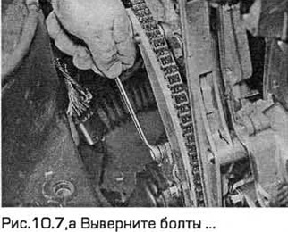
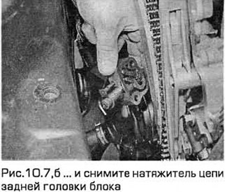
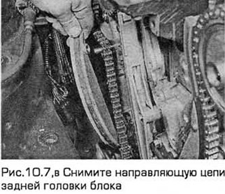
7. Unscrew the bolts of the rear cylinder head chain tensioner. Remove the chain guide from its hinge (see Fig. 10.7, a-c).
Note: On early production models, an adapter plate may be installed between the tensioner and the cylinder block.
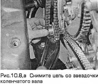
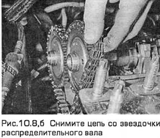
8. Remove the chain from the crankshaft and camshaft sprockets (see Fig. 10.8,a,b). If you install the same chain again, it should have the appropriate marks.
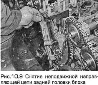
9. Remove the fixed chain guide bolts (see Fig. 10.9).
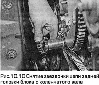
10. Pull the sprocket off the crankshaft, taking into account which side it is installed on. Mark it for installation in the same position (see Fig. 10.10).
11. To remove the front head chain, turn the shaft so that its key is at the 11 o'clock position. The corresponding mark on the front head intake camshaft sprocket should be at the 9 o'clock position. A similar mark on the front head exhaust camshaft sprocket should be at the 12 o'clock position.
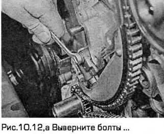
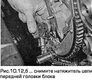
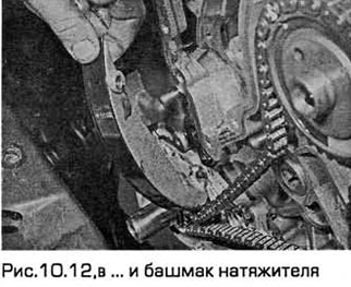
12. Unscrew the front cylinder head chain tensioner bolts. Remove the chain guide from its hinge (see Fig. 10.12, a-c).
Note: On early production models, an adapter plate may be installed between the tensioner and the cylinder block.
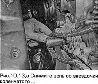
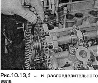
13. Remove the chain from the crankshaft and camshaft sprockets (see Fig. 10.13, a, b). If you install the same chain again, it should have the appropriate marks.
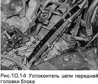
14. Remove the fixed chain guide bolts (see Fig. 10.14).
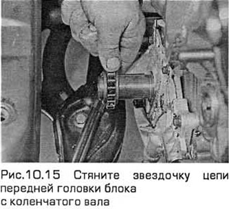
15. Pull the sprocket off the crankshaft, taking into account which side it is installed on. Mark it for installation in the same position (see Fig. 10.15).
Inspection
Note: All required components must be labeled for proper installation.
16. Clean and dry all components.
17. Inspect the chain tensioners and guides for excessive wear or other damage. There should be no deep chain nicks on the guides.
18. Inspect the chains for excessive wear. Hold them horizontally and check for play in the chain links. Replace the chains if necessary.
19. Check the crankshaft and camshaft sprockets for excessive wear or other damage. The camshafts are integral with the sprockets. Therefore, if the sprocket is worn, the shaft must be replaced.
20. Before installing the tensioners, their pistons must be compressed and locked. Insert a small screwdriver into the tensioner hole and release the ratchet mechanism. Clamp the tensioner in a vice with soft jaws and press the piston. Into the cylinder. Then lock the piston by inserting a piece of wire with a diameter of 1.5 mm into a special hole.
Installation
21. If necessary, turn the crankshaft so that the key is at 11 o'clock, corresponding to the installation of the front head chain.
22. Check the marks on the front cylinder head camshaft sprockets. The intake camshaft sprocket should be at the 9 o'clock position and the exhaust camshaft sprocket should be at the 12 o'clock position.
23. Install the fixed chain guide and tighten the bolts.
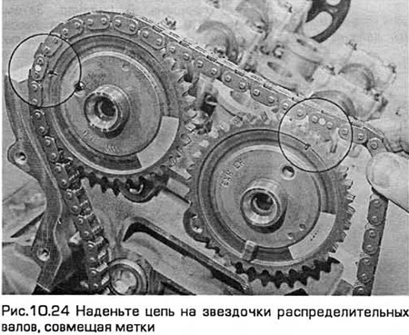
24. Place the chain on the camshaft sprockets, aligning the marks (see Fig. 10.24).
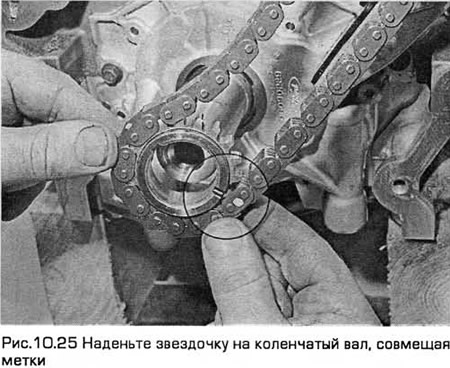
25. Engage the crankshaft sprocket with the chain, aligning the marks, then place the sprocket on the crankshaft, pressing it onto the key (see Fig. 10.25). In this case, the front branch of the chain should be pressed against the fixed guide, and the rear branch should be loosened.
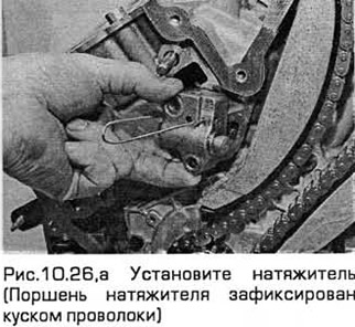
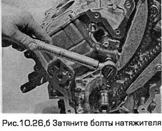
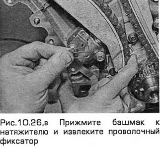
26. Install the sliding guide on its hinge, then install the tensioner (and adapter plate, if any). Tighten the bolts to the specified torque. Check that the marks are aligned, then unlock the tensioner piston. Due to the high tension spring force, it is necessary to press the guide against the tensioner while pulling out the locking piece of wire, and then gradually release it (see Fig. 10.26, a-c).
27. If necessary, turn the crankshaft so that the key is at the 3 o'clock position, corresponding to the installation of the rear head chain.
28. Place the sprocket on the crankshaft.
29. Check the marks on the rear cylinder head camshaft sprockets. The exhaust camshaft sprocket should be at the 12 o'clock position and the intake camshaft sprocket at the 3 o'clock position.
30. Install the fixed chain guide and tighten the bolts.
31. Place the chain on the crankshaft and camshaft sprockets, aligning the marks. The front chain branch should be pressed against the fixed guide, and the rear branch should be loose.
32. Install the sliding guide on its hinge, then install the tensioner (and adapter plate, if any). Tighten the bolts to the specified torque. Check that the marks are aligned, then release the tensioner piston.
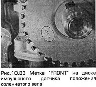
33. Place the crankshaft position pulse sensor disc on the shaft, aligning the keyway (with the blue mark) of the disc with the key. The disc should have the marks "2.5 L" and "FRONT" (see Fig. 10.33).
34. Temporarily install the crankshaft pulley bolt and rotate the shaft so that its key is at the 11 o'clock position.
Note: After turning the crankshaft, the marks on the chain move away from the marks on the sprockets, but the marks on the camshaft sprockets must be directed towards each other.
35. Install the chain cover (paragraph 9).
[This article was borrowed from the website: FORDBOOK.RU]