Contents: Inspection ↳ Replacement ↳ Right support ↳ Left support ↳ Front support (roll limiter) ↳ Rear support (roll limiter) ↳
1. These bearings do not require attention often, however, a damaged or broken bearing must be replaced immediately. Otherwise, the loads occurring in the power transmission may cause damage or wear.
2. The supports can be removed and installed separately. However, if several supports need to be disassembled, such as when removing the power unit, then such a removal and installation procedure must be performed in a strict sequence (Chapter 2B).
Inspection
3. To access the right engine mount, remove the screws securing the coolant reserve tank to the right front fender inner panel. Move the tank to the side. To access the left engine mount, remove the battery (Chapter 5A) and air cleaner (Chapter 4A). To access the front and rear engine mounts, apply the parking brake, raise the front of the vehicle, and support it. Use a mirror.
4. Inspect the bearings for cracks in the rubber, hardening, or separation of the rubber from the metal base. If such signs are found, replace the bearing.
5. Check the tightness of all support nuts and bolts, using a torque wrench if necessary.
6. Check the possibility of relative displacement of the bracket of each support and the power unit or body. To do this, move the supports with a power screwdriver or crowbar. If the displacement is noticeable, check the tightening (with a torque wrench) of the support fasteners. If the play remains, then it is necessary to find and replace the worn components.
Replacement
Right support
7. Remove the water pump pulley cover bolts on the top of the engine.
8. Remove the screws and move the coolant reserve tank to the side.
9. Raise the engine with a hoist. If you only need to remove the right support, you can carefully support the engine with a jack using a wooden pad placed under the pan.
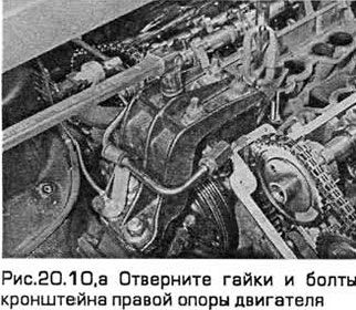
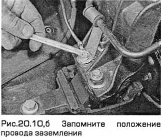
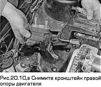
10. Mark the position of the support bracket. Unscrew the nuts and remove the bracket. Remember the position of the ground wire (see Fig. 20.10.a-c). Note: These nuts are self-locking and must be replaced.
11. Remove the support bolts from the body panel.
12. Install the new support onto the body panel and tighten the bolts to the specified torque.
13. Install the bracket on the support and the engine in the position marked during removal. Tighten the new nuts to the specified torque. Install the ground wire correctly.
14. Lower the vehicle and remove the lift.
15. Install the reserve tank and tighten its screws.
16. Install the water pump pulley cover on top of the engine. Screw in the bolts.
Left support
17. Remove the battery (Chapter 5A).
18. Remove the air cleaner (Chapter 4A).
19. Remove the coolant pump pulley cover bolts on the top of the engine.
20. Raise the transmission with a lift. If you only need to remove the left support, you can carefully support the transmission with a jack through a wooden spacer.
21. Mark the position of the support bracket. Unscrew the nuts from the transmission studs (see Fig. 20.21).
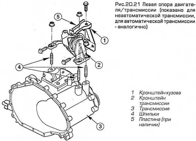
Note: These nuts are self-locking and will need to be replaced.
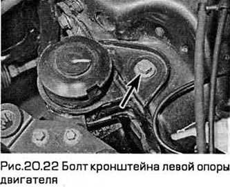
22. Remove the support bolts from the body panel (see Fig. 20.22).
23. Install the new support onto the body panel and tighten the bolts to the specified torque.
24. Install the bracket onto the support and transmission in the position marked during removal. Tighten the new nuts to the specified torque.
25. Lower the vehicle and remove the lift.
26. Install the water pump pulley cover on top of the engine. Screw in the bolts.
27. Install the battery (Chapter 5A) and air cleaner (Chapter 4A).
28. Connect the negative battery cable (Chapter 5, paragraph 1).
Note: To restore the engine management system settings due to the battery being disconnected, a mileage of approximately 16 km is required. In this case, the engine may not operate normally.
Front support (roll limiter)
29. Apply the parking brake. Raise the front end and place it on supports.
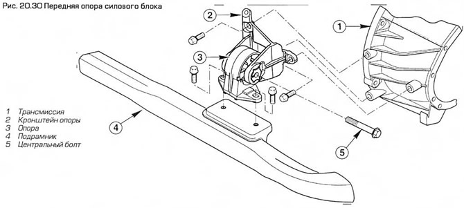
30. Unscrew the bolts securing the front support to the subframe, as well as the central bolt. Remove the support (see Fig. 20.30).
31. If necessary, remove the bracket bolts from the transmission and remove it.
32. Install the bracket onto the transmission and tighten the bolts to the specified torque.
33. Install the new front support onto the bracket and insert its center bolt.
34. Screw in the bolts securing the front support to the subframe and tighten them to the required torque.
35. Tighten the center bolt to the specified torque.
36. Lower the vehicle to the ground.
Rear support (roll limiter)
37. Apply the parking brake. Raise the front end and place it on supports.
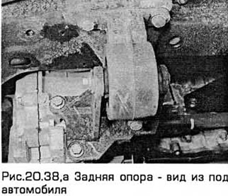
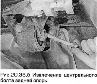
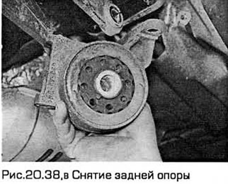
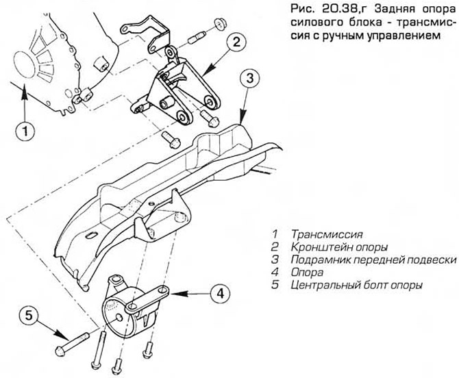
38. Unscrew the rear support mounting bolts/nuts, as well as the central bolt. Remove the support (see Fig. 20.38, a-g). If necessary, slightly lift the transmission with a jack through a wooden pad. Note that on some models with an automatic transmission, an additional rubber damper is installed under the subframe.
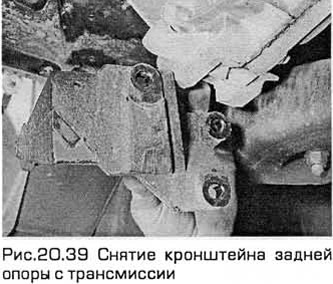
39. If necessary, unscrew the bracket bolts from the transmission and remove it (see Fig. 20.39).
40. Install the bracket onto the transmission and tighten the bolts to the specified torque.
41. Install the new rear support onto the bracket and tighten the bolts/nuts to the specified torque. On models with automatic transmission, install the additional rubber damper onto the subframe bracket and tighten the nuts to the specified torque.
42. Insert the center bolt and tighten it to the specified torque.
The original post is on the web portal: FordBook