Front block head
Withdrawal
1. Disconnect the negative battery cable (chapter 5, par 1).
2. Turn out bolts of the plastic cover fixed on top of a forward head of the block. Remove the cover and release the coolant hose.
3. Disconnect the crankcase ventilation hoses from each side of the air intake duct from the air cleaner to the throttle body.
4. Release a collar and disconnect a vacuum hose.
5. Release two collars and disconnect an inlet air line from the throttle body and an air cleaner. Remove the air duct.
6. Disconnect the two brake booster vacuum hoses from the top section of the intake manifold.
7. Disconnect the throttle cable bracket and RVG system valve. To do this, release the latch and disconnect the wiring connector. Disconnect the wiring from the idle air control valve and throttle position sensor. Disconnect the vacuum hose from the RVG system valve. Then turn out bolts and remove the valve. Remove the gasket.
8. Disconnect the positive crankcase ventilation hose and disconnect the wiring and vacuum hose from the electronic vacuum regulator.
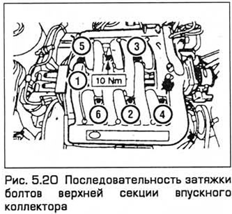
9. Turn out bolts in sequence, return shown on fig. 5.20, and remove the top section of the intake manifold. Remove the pads.
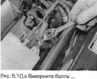
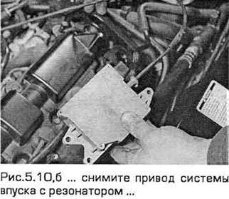
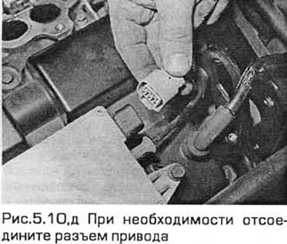
10. Turn out bolts of fastening of a drive of system of an admission with the resonator to a cover of a head of the block. Unfasten the wiring and cable and slide them to the side. Disconnect wiring if necessary (see fig.5.a-d).
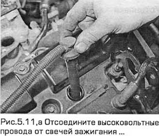
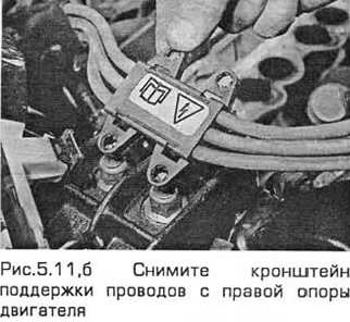
11. Taking into account the position of high-voltage wires and, if necessary, marking them. disconnect the wires from the spark plugs. Remove wire support bracket from right engine mount (see Fig.5.11, a, b).
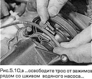
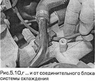
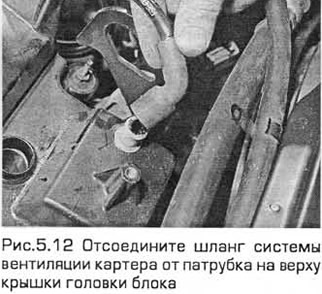
12. Release a hose of system of cooling from a collar and remove an arm. Disconnect the crankcase ventilation hose from the fitting on top of the head cover (see fig.5.12).
13. Detach the wiring from the head cover.
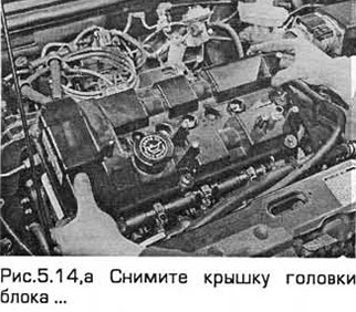
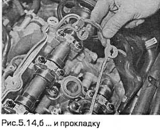
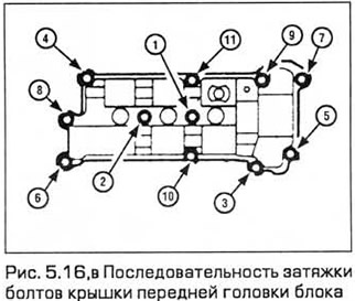
14. In the reverse order shown in fig. 5.16c, unscrew the bolts of the block head cover in sequence, and then remove the cover and gaskets (see Fig.5.14, a,b).
Installation
15. Make sure. that the mating surfaces of the cover and block head are dry and clean. Apply an 8 mm bead of sealant to the joints between the MHR cover and the block head.
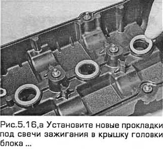
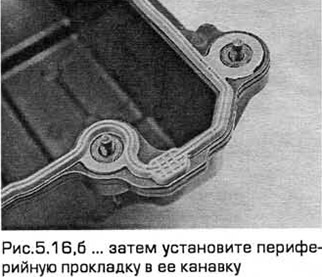
16. Install new gaskets under the spark plugs in the head cover. Then install the peripheral gasket in its groove (see Fig. 5.16, a, b). Establish a cover of a head of the block and tighten bolts the demanded moment in the sequence shown in fig. 5.16, c. Make sure that the O-rings are correctly installed on the bolts.
17. Attach the wiring to the block head cover. Establish an arm and fix a collar a hose of system of cooling.
18. Attach the high voltage wires to the spark plugs and secure them to the bracket located on the right engine support.
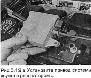
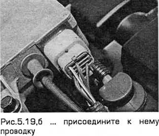
19. Install the intake system actuator with a resonator and connect the wiring to it (see Fig. 5.19, a, b).
20. Establish the top section of an inlet collector together with linings. Torque tighten the bolts as shown in fig. 5.20.
21. Install the RVG system hose. Connect the vacuum hose and wiring to the electronic vacuum regulator.
22. Install the RVG system valve on a new gasket and tighten the bolts. Connect the vacuum hose. Connect wiring to idle air control valve and throttle position sensor. Install the retainer. Install the cable bracket.
23. Attach two vacuum hoses to the upper section of the intake manifold.
24. Connect the intake duct to the throttle body and air cleaner and tighten the clamps.
25. Attach a vacuum hose and tighten a collar.
26. Connect the crankcase ventilation hoses on both sides of the intake duct coming from the air cleaner to the throttle body.
27. Install the plastic cover on top of the front block head. Fix a hose of system of cooling. Tighten the cover bolts.
28. Connect the negative battery cable (chapter 5, par 1).
Note: To restore the settings of the engine management system due to battery disconnection, a mileage of about 15 km is required. In this case, the engine may not work normally.
Rear block head
Withdrawal
29. Disconnect the negative battery cable (chapter 5, par 1).
30. Turn out bolts of a plastic cover (coolant pump pulley), attached to the top of the front block head. Remove the cover and release the coolant hose.
31. Disconnect the crankcase ventilation hoses from each side of the intake duct from the air cleaner to the throttle body.
32. Release a collar and disconnect a vacuum hose.
33. Release the two clamps and disconnect the intake duct from the throttle body and air cleaner. Remove the air duct.
34. Disconnect the two brake booster vacuum hoses from the top section of the intake manifold.
35. Remove the throttle cable bracket and RVG system valve. To do this, release the latch and disconnect the wiring connector. Disconnect the wiring from the idle air control valve and throttle position sensor. Disconnect the vacuum hose from the RVG system valve. Then turn out bolts and remove the valve. Remove the gasket.
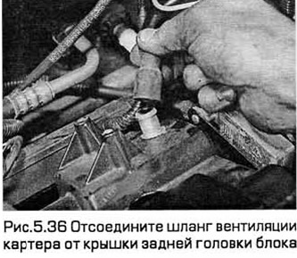
36. Disconnect the positive crankcase ventilation hose and disconnect the wiring and vacuum hose from the electronic vacuum regulator. Also disconnect the crankcase ventilation hose from the cover on its top (see fig.5.36).
37. Turn out bolts in sequence, return shown on fig. 5.20, and remove the top section of the intake manifold. Remove the pads.
38. Taking into account the position of the high-voltage wires and, if necessary, marking them, disconnect the wires from the spark plugs. Remove the wire support bracket from the right engine mount.
39. Turn out bolts and remove a trench of conducting of atomizers.
40. Turn out bolts and remove knot of the coil of ignition. Disconnect the wiring and release it from the fasteners. Remove the ground wire and RFI damper.
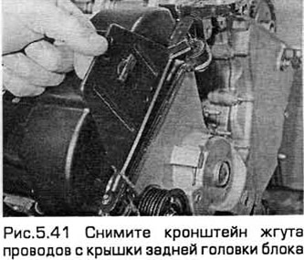
41. Turn out a bolt and remove a forward bracket of a plait of wires from a cover of a forward head of the block. Then remove the rear wiring harness bracket from the rear head cover (see fig. 5.41).
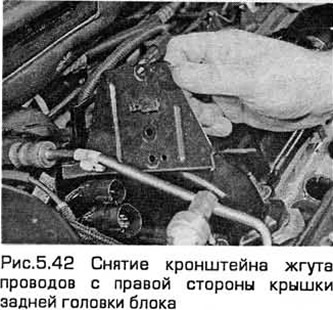
42. Disconnect the wiring, then remove the wire harness bracket bolts from the rear head cover (see fig. 5.42).
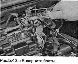
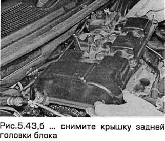
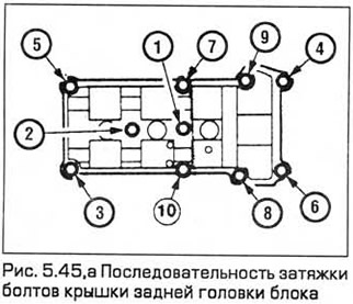
43. In the reverse order shown in fig. 5.45, a, successively unscrew the bolts of the block head cover, and then remove the cover and gaskets (see fig. 5.43.a,b).
Installation
44. Make sure. that the mating surfaces of the cover and block head are dry and clean. Apply an 8 mm bead of sealant to the joints between the MHR cover and the block head.
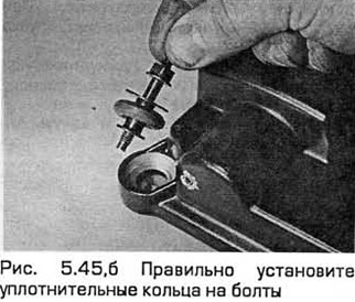
45. Install new gaskets under the spark plugs in the head cover. Then install the peripheral gasket into its groove. Establish a cover of a head of the block and tighten bolts the demanded moment in the sequence shown in fig. 5.45, a, Watch for the correct installation of O-rings on the bolts (see Fig. 5.45, b).
46. Attach the wiring chute to the rear head cover of the unit.
47. Install and secure the front wire harness bracket to the front head cover. Then install and secure the rear wiring harness bracket to the rear head cover.
48. Install the ignition coil assembly and tighten the bolts. Connect the wiring and secure it. Install the ground wire and RFI damper.
49. Install the injector wiring chute and tighten the bolts.
50. Connect the high voltage wires to the spark plugs and secure them to the bracket located on the right engine mount.
51. Establish the top section of an inlet collector together with linings. Torque tighten the bolts as shown in fig. 5.20.
52. Install the RVG system hose. Connect the vacuum hose and wiring to the electronic vacuum regulator.
53. Install the RVG system valve on a new gasket and tighten the bolts. Connect the vacuum hose. Connect wiring to idle air control valve and throttle position sensor. Install the retainer. Install the cable bracket.
54. Attach two vacuum hoses to the upper section of the intake manifold.
55. Attach the intake duct to the throttle body and air cleaner and tighten the clamps.
56. Attach a vacuum hose and tighten a collar.
57. Connect the crankcase ventilation hoses on both sides of the intake duct coming from the air cleaner to the throttle body.
58. Install the plastic cover on top of the front block head. Fix a hose of system of cooling. Tighten the cover bolts.
59. Connect the negative battery cable (chapter 5, par 1). Note: To restore the settings of the engine management system due to battery disconnection, a mileage of about 16 km is required. In this case, the engine may not work normally.
Visitor comments