Removal
Loosen the timing belt tension (see the corresponding description in the section "Removing the timing belt").
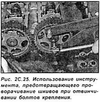
Remove the timing belt. Do not rotate the crankshaft with the timing belt removed. Unscrew the camshaft pulley mounting bolts and remove the pulleys (see Fig. 2C.25).
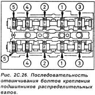
Working in a specific sequence, loosen the camshaft bearing cap bolts by half a turn each pass until the bolts are completely unscrewed. This is necessary to gradually and evenly relieve the valve spring pressure (see Fig. 2C.26).
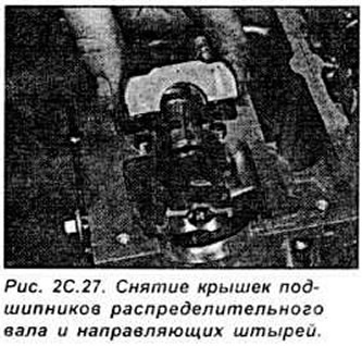
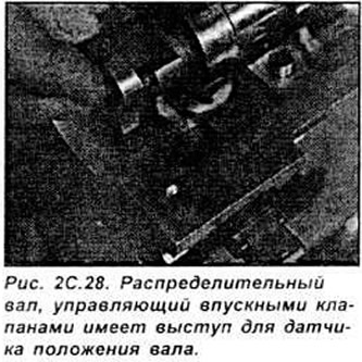
Remove the covers, checking their markings and the presence of guide pins, then remove the camshafts and oil seals. The camshaft controlling the intake valves can be identified by the protrusion for the camshaft position sensor (see Fig. 2C.27, 2C.28).
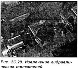
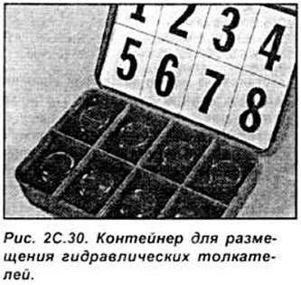
Using a rubber suction cup, remove each hydraulic tappet and turn it upside down to prevent oil from leaking out of the tappet. Place the tappets in a suitable container which should be filled with clean engine oil. Position the hydraulic tappets so that they can be installed in their places (see Fig. 2C.29, 2C.30).
Examination
Check the condition of the camshafts and hydraulic tappets.
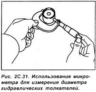
Measure the outside diameter of the tappets with a micrometer, as well as the presence of taper in the cylindrical part of the tappet.
If you hear valve knocking when starting a cold engine, but the hydraulic tappets are in good working order, you need to replace the engine oil and filter and use only good quality engine oil of the required viscosity.
Check the camshaft lobes for scratches, pitting and wear. If there are any defects, the camshaft must be replaced.
Check the condition of the camshaft bearings and cylinder head bearings for wear.
Measure the diameter of each camshaft journal at several points using a micrometer. If any journal diameter is smaller than required, the camshaft must be replaced.
To check the camshaft bearing clearance, remove the hydraulic tappets and, using a suitable solvent, thoroughly clean the bearing running surfaces, then install the camshafts and place a length of Plastigage along each camshaft bearing journal. Install the bearing caps and tighten them to the specified torque. Remove the bearing caps and measure the width of the dipstick with a scale. Based on the width of the crushed dipstick, use the scale to determine the clearance. Using a soft tool, remove the dipstick from the camshaft journals.
If the operating clearance of any bearing exceeds the permissible limits, replace the camshaft with a new one and repeat the measurements. If the clearance again exceeds the permissible value, the head must be replaced.
To check the camshaft play, remove the hydraulic lifters, clean the bearing surfaces, and install the camshafts and bearing caps. Measure the play using a dial indicator with the measuring tip resting on the right end of the camshaft.
Move the camshaft to the indicator, set the indicator to zero and move the camshaft as far away from the indicator as possible. The measured clearance will be displayed on the indicator scale. If the clearance exceeds the permissible value, repeat the measurement. If the clearance exceeds the permissible value again, the head must be replaced.
Installation
Lubricate the hydraulic tappet seats in the cylinder head and the hydraulic tappets. Insert the hydraulic tappets into the seats they were in before removal.
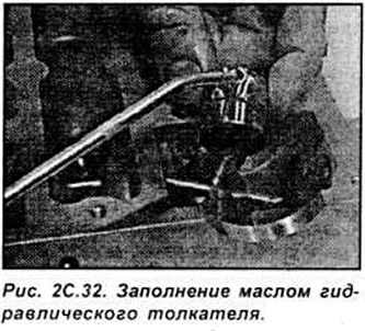
Caution: If new hydraulic lifters are used, they must be filled with engine oil before installation.
Lubricate the camshaft bearings and cams with engine oil and install the shafts in place, aligning the shafts so that the slots in the left end of the shafts are parallel and higher than the mating surface of the cylinder head.
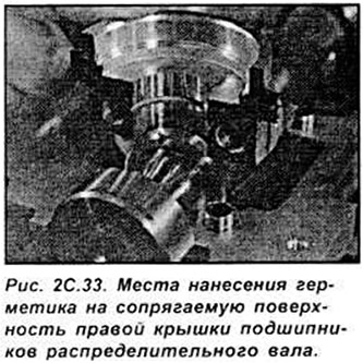
Check that the guide pins are in place and that the mating surface is completely clean. Apply a thin coat of Loctite 518 to the mating surfaces of the right-hand camshaft bearing caps. Install new camshaft oil seals (see Fig. 2C.34).
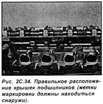
All camshaft bearing caps are marked with one digit indicating the cap number. The bearing caps of the camshaft controlling the intake valves are marked with digits from 1 to 4, and the exhaust camshafts are marked with digits from 5 to 9. Each cap must be installed so that the numbered side surfaces are directed outward from the engine (see Fig. 2C.34).
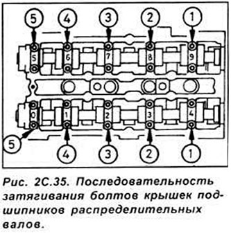
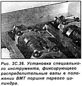
Tighten the bearing cap bolts gradually and in a specific sequence, turning each bolt half a turn at a time until each cap contacts the cylinder head. Then, in the same sequence, tighten the bolts in two stages to the specified torque. Gradual and uniform tightening of the bolts is necessary to uniformly compress the valve springs (see Fig. 2C.35, 2C.36).
Wipe off any excess sealant to prevent it from getting into the oil passages. The engine can be started no earlier than one hour after applying the sealant.
Install new camshaft oil sealing rings
Install the camshaft pulleys on the shafts, tightening the pulley mounting bolts by hand. Install the toothed belt on the pulleys and finally tighten the bolts, using a special tool to hold the pulleys from turning. Further installation is performed in the reverse order of removal.
The original post is on the web portal (www.FordBook.ru)