Withdrawal
Attention. The procedure for removing the cylinder head with intake and exhaust manifolds is given. This greatly simplifies the process of removing the head, but it is desirable to use a lifting mechanism.
Depressurize the fuel system.
Remove the ground wire from the battery. Remove the elements of the air supply system to the engine.
Equalize the pressure in the fuel tank by removing the filler cap. Then unscrew the fuel supply and return pipes. Remove the accelerator cable from the throttle. Remove the auxiliary drive belt.
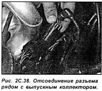
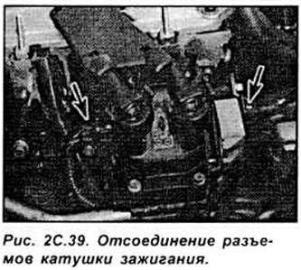
Remove the power steering pump. Remove the three screws securing the electrical wiring at the back of the manifold. Release the wiring clamp and disconnect the large electrical connector (next to the fuel pressure regulator). Release the electrical connectors on each side of the ignition coil, and one connector from the bottom front of the thermostat housing to disconnect the coolant temperature sensor (see fig. 2C.38, 2C.39).
Mark and disconnect the vacuum hoses as follows:
- one from the back of the throttle body (no need to disconnect the second hose going to the fuel pressure regulator)
- one from the connection on the left end of the intake manifold
- brake booster hose
Remove the bolts on both sides of the exhaust manifold heat shield.
Remove the bolt securing the air filter housing to the engine/gearbox front mounting mount, then disconnect the vacuum hose.
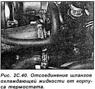
Drain the coolant from the cooling system. Disconnect all coolant hoses from thermostat housing (see fig. 2C.40).
Remove the two nuts securing the front exhaust pipe to the front of the exhaust manifold and disconnect the oxygen sensor. Support the weight of the power unit using a jack with a wooden pad.
Remove the toothed belt, both camshafts and remove the hydraulic tappets. Remove the inner toothed belt shield.
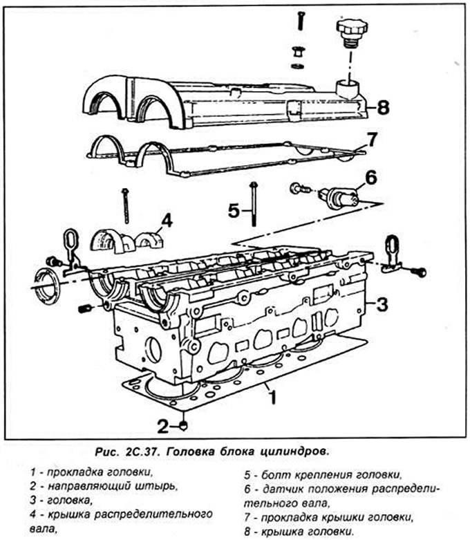
Evenly and gradually in a certain sequence, loosen the ten cylinder head bolts (Torx key T55). Remove the cylinder head and head gasket.
Preparing the head for installation
The mating surfaces of the head and cylinder block must be perfectly clean. Use a hard plastic or wooden scraper to clean them. Be careful when cleaning as aluminum alloy is very easy to damage. Check that carbon deposits have not entered the oil and water channels, this is especially important for the lubrication system, since carbon deposits can block the oil supply to engine components. Clean channels if necessary. Check the mating surfaces of the cylinder head and block for nicks, deep scratches or other damage. If the defects are small, they can be removed by machining, but in case of significant defects, the parts must be replaced.
Using a metal ruler and feeler gauge, check the flatness of the mating surfaces.
Clean the bolt holes in the block. Screwing a bolt into an oil-filled hole can rupture the block due to hydraulic pressure.
Installation
Wipe mating surfaces of the head and cylinder block.
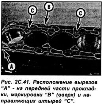
Check that the new cylinder head gasket is of the same type. what is the original and what is the marking "TOR" (or "OBEN") directed upward. Position the new cylinder head gasket on the surface of the cylinder block on the guide pins. Check that the holes are correctly aligned with the channels of the cooling and lubrication system (see fig. 2C.41).
To prevent the possibility of valve and piston contact, turn the crankshaft so that the piston of the first cylinder is set 20 mm below the TDC position.
To simplify the process of installing a heavy head in place, make a pair of M10 threaded posts, about 90 mm long, with a slot for a screwdriver at one end (you can use two old head bolts, after cutting off the bolt heads and sawing a slot for a screwdriver). Screw these struts into the holes at diagonally opposite corners of the cylinder block surface. slots for a screwdriver upwards so that they can be unscrewed after the head is installed. The posts should protrude 70 mm above the gasket.
Install the head by sliding it down the uprights and place it on the guide pins. Unscrew the stands.
Install new cylinder head bolts and hand tighten.
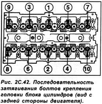
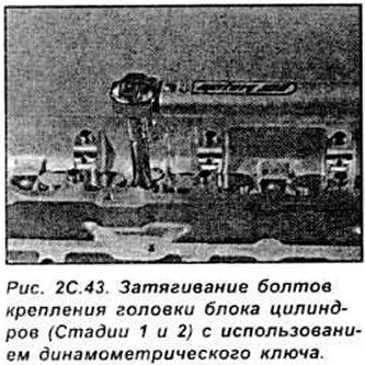
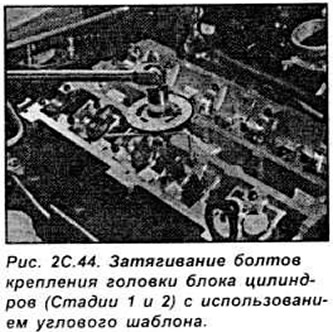
Gradually and in a certain sequence, tighten the head bolts in several stages (see fig. 2C.42, 2C.43).
Install hydraulic tappets. camshafts, camshaft oil seals and pulleys.
Temporarily install the crankshaft pulley, and rotate the crankshaft clockwise to set the pulley marks 8 to the TDC position of the piston of the first cylinder. Install toothed belt and covers. checking the alignment of the camshaft and adjust the toothed belt tension. Further installation is carried out in the reverse order of removal.
Visitor comments