Contents: Cleaning ↳ Examination ↳
1. A thorough cleaning of the cylinder head(s) and the remaining valve components, together with a detailed inspection, will help you determine the amount of valve maintenance work required during an engine overhaul.
Cleaning
2. Scrape all traces of old gasket material and seal from the head gasket and the sealing surfaces of the intake and exhaust manifolds. Be very careful not to scratch the head.
3. Remove all parts built into the cooling channels.
4. Brush the holes with a stiff wire brush to remove any deposits that may have accumulated on the walls.
5. Go through the threaded holes with a tap of the appropriate size to remove rust and residues of thread seals. If possible, remove chips and dirt resulting from processing with compressed air.
6. If necessary, process the threaded connections of the rocker arm axles with taps of the appropriate sizes.
7. Wash the cylinder head with solvent and dry thoroughly.
8. Clean the valve levers, pivot pins, bolts and pushrods with solvent and dry thoroughly (do not mix them during cleaning).
9. Wash all valve springs, screens, crackers and plates with solvent and dry thoroughly.
10. Clean off any deposits that may have formed on the valves, then use a power wire brush to clean the deposits off the valve heads and stems. Again, make sure you have not mixed up parts from different valves.
Examination
Cylinder head
11. Carefully inspect the cylinder head for cracks, obvious coolant leaks, and other damage. If you find cracks, it will have to be replaced with a new one.
12. Using a straightedge and feeler gauge, check for possible distortion of the surface adjacent to the cylinder head gasket (see figure).
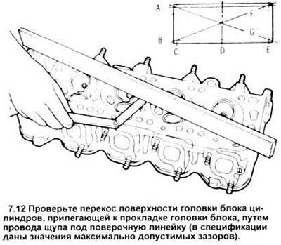
If the distortion exceeds the specification limit, the surface should be treated.
13. In each of the combustion chambers, check the valve seats. If they have pitting, cracks or burnouts, then the cylinder head should be replaced.
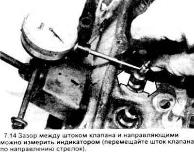
14. Check the valve stem to guide clearance by measuring the lateral movement of the valve stem with an indicator connected directly to the head (see figure). The valve should be in the guide and approximately 1.588 mm (1/16 in) above the seat. Divide the full stroke of the valve stem, recorded by the indicator leg, by 2 to obtain the actual clearance.
Valves
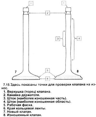
15. Carefully inspect the outside of the valve for premature wear, deformation, cracks, corrosion spots, and burn marks (see figure). Check the valve stem for galling and abrasion, and the neck for cracks. Turn the valve and check if it is bent. The end of the stem may have pitting corrosion and areas of intense wear. If any of the above is found, the valves should be replaced.
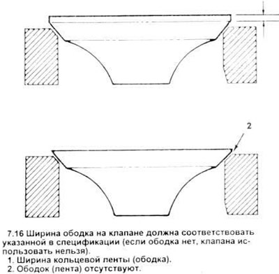
16. Measure the width of the edge of the ring band of each valve (see figure). The valve should be replaced with a new one if the width of this band is less than 0.794 mm (1/32 inch).
Valve elements
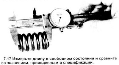
17. Check all valve springs for wear and pitting. Measure the free length and compare with the specification (see figure). If the spring is shorter than the required length, it is "settled" and can no longer be used. The compression force of each spring is determined using a special clamp; based on the test results, a decision is made on whether it can be used in a reconditioned engine.
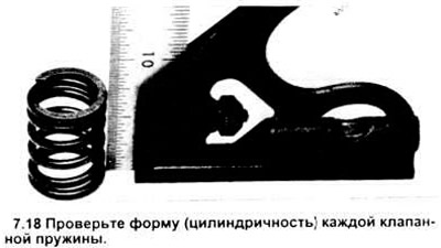
18. Place each spring end-on on a flat surface and check its shape. If any spring is deformed or "sagged", replace it with a new one.
19. Visually inspect the crackers and spring plates for wear and cracks. Replace any questionable parts with new ones, since their failure in a running engine will result in serious damage.
Valve lever elements
20. Check the lever faces (the contact surfaces with the pushrod ends and valve stems) for pitting, wear, galling, scratches and scoring. Also check the rotating part of the lever contact surface and the pivot pin. Inspect each lever and bolt for cracks.
21. Check the ends of the push rods for abrasion and intense wear. Roll each rod on the glass to determine the degree of its curvature.
22. Check the valve lever studs in the cylinder heads - thread damage and incorrect installation are possible.
23. Any damaged or badly worn parts should be replaced with new ones.
25. If no intensively worn parts are found, and the outer surfaces and valve seats are in good condition, then the valve group can be installed in the cylinder heads without any special modifications.