2. The camshaft cannot be removed until the engine is removed. If the camshaft needs to be replaced (or balance shaft), then first remove the engine (section 4).
3. After removing the engine from the car and installing it on the stand, remove the camshaft drive chain and sprocket section 12 or chapter 2 part B depending on what engine you have).
4. Remove and fold the valve lifters in order (chapter 2A or 2B).
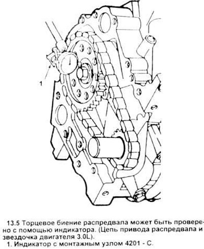
5. On late model 3.8L four-cylinder engines and all 3.0LV6 engines, install a dial gauge on engines and check camshaft end-to-end runout (see picture). Compare with the value given in the specification. If the value is too high, a new thrust plate must be installed. Early 3.8L engines have thrust springs, so they do not need to be adjusted.
6. Remove the bolts securing the thrust plate to the camshaft and/or balancer shaft and disconnect the plate from the engine block.
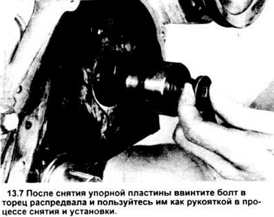
7. To remove the camshaft, screw a long bolt into its end, which you will use as a handle (see picture). The thread there is metric - use a bolt with the appropriate diameter and thread pitch.
8. To remove the balance shaft (only for 3.8LV6 engines), remove the threaded bar and carefully guide the shaft when removing it from the block.
9. After the camshaft is removed from the engine (or balance shaft), clean it with solvent, and carefully inspect the bearing journals for wear, pitting, and galling. If the necks are damaged, then. most likely, the bearing seats in the block are also damaged.
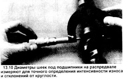
10. If their condition is satisfactory, measure the bearing journals with a micrometer (see picture) to determine their size, as well as possible deviations from roundness. The inside diameter of a bearing can be determined using a telescopic gauge in combination with a micrometer. To find the oil clearance for each bearing, compare the obtained numerical values of the shaft journal diameters and the bearing inner diameter. Compare the resulting gap value with the value specified in the specification. If this value is too high in at least one of the bearings, then the bearings should be replaced with new ones.
11. Check the camshaft cams and the presence of tempering colors. nicks, gouges, pitting and heavy wear. If the cams are in good condition and their lift measurements are within the specifications, the camshaft can be reinstalled (given that the bearing journals are in satisfactory condition).
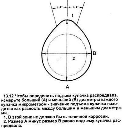
12. Camshaft lobe lift can be checked without removing the camshaft from the engine (chapters 2A or 2B) or after removal. The following procedure will accurately indicate the amount of cam wear after the camshaft has been removed and can be used to verify cam lift measurements taken with the camshaft not removed. Measure the maximum (A) and minimum (IN) diameters of each cam with a vernier caliper or micrometer and record the results (see picture). Their difference is the rise of the cam. If the lift of at least one of the cams is less than the value specified in the specification. replace the entire camshaft.
13. Replacing the camshaft and/or balancer shaft requires a special tool.
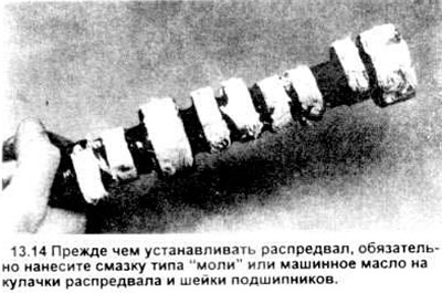
14. Lubricate the cams and journals of the camshaft and/or journals of the balance shaft with grease based "moth" or engine oil (see picture).
15. Lower the camshaft or balancer shaft into the engine. Be careful not to scratch the bearings.
16. Apply moth grease to the back of the thrust plate, then install it on the block and tighten the mounting bolts to the correct torque.
17. Install the camshaft drive chain, sprockets, chain tensioner, front cover, oil seal and crankshaft pulley (see if necessary chapter 2B or section 12).
18. Install the oil pan (chapter 2A or 2B).
19. Lubricate the valve lifters with clean engine oil and install them in the block.
20. On four-cylinder engines, install the cylinder head (chapter 2A).
21. The subsequent installation steps are carried out in the reverse order of disassembly.
22. Before starting the engine, add the correct amount of oil of the appropriate brand, coolant and install a new oil filter (Chapter 1).
Visitor comments