Contents: Removal ↳ Installation ↳
Removal
1. To carry out these works the engine must be removed (section 4).
2. Remove the oil pan (see chapter 2A).
3. Remove the crankshaft pulley (see section 13).
4. Unscrew the front cover mounting bolts (see figure). Move the cover away from the unit with a large screwdriver or a lever bar (see figure).
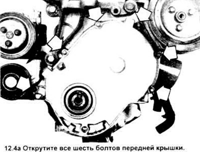
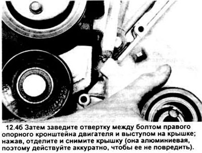
Caution: Only engage the lever at the points shown in the diagram, otherwise the cover gasket surface may be damaged, resulting in oil leaks.
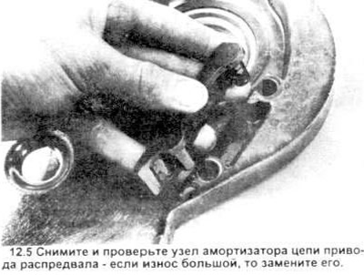
5. Remove the camshaft drive chain shock absorber assembly from the cover (see figure) and determine the degree of its wear. If significant wear occurs, replace it.
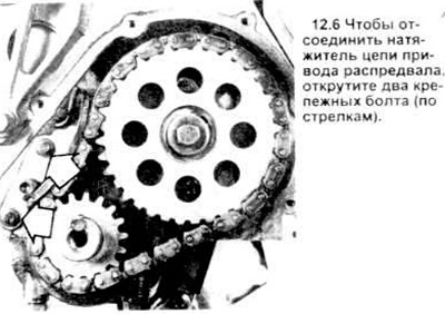
6. Remove the bolts and disconnect the camshaft timing chain tensioner (see illustration). Check the tensioner bearing surface (the surface on which the chain runs). If there are grooves deeper than 1.524 mm (0.06 in), replace the tensioner.
7. To take up the slack on the left side of the chain, turn the crankshaft counterclockwise (shown from the front of the engine).
8. Make a mark on the engine block approximately halfway along the left side of the chain, then measure from that point to the chain itself.
9. Turn the crankshaft in the opposite direction to take up the slack in the right side of the chain. Pull the left side of the chain outward with your finger and make a second measurement of the distance from the mark on the block.
10. To determine chain sag, subtract the first measurement from the second measurement. Compare with the specification. If the sag is too great, replace the chain and sprockets.
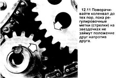
11. Turn the crankshaft until the adjustment marks on the sprockets are aligned (see figure). The marks are small recesses drilled at the outer edges.
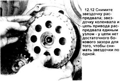
12. Unscrew the bolt securing the sprocket to the camshaft and remove the washer. If the crankshaft rotates, screw a pair of flywheel bolts into its rear end and place a screwdriver between them. Pull both sprockets and the camshaft drive chain forward (see figure) and remove them as a single unit.
Installation
Camshaft Drive Chain and Sprockets
13. Use a scraper to remove any remaining gasket and sealant from the cover and engine block, then clean the adjacent surfaces with a rag soaked in solvent or acetone. Clean the target and sprockets with solvent.
14. Make sure that the guide pin in the camshaft and the Woodruff key in the crankshaft are in place; then place both sprockets and the camshaft drive chain on the shafts, aligning the corresponding marks (see figure).
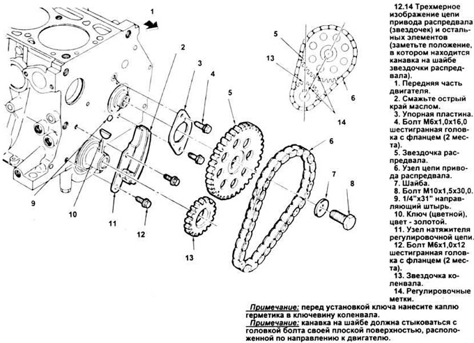
Each sprocket has a slot that must be aligned with the camshaft pin or crankshaft key. Tighten the camshaft bolt, installing the washer and tighten the bolt to the specified torque value.
Note: The camshaft sprocket bolt washer should be installed with the groove facing outward, toward the bolt head (this means the flat side of the washer should face the sprocket). Install the tensioner and tighten the bolts to the specified torque value. Lubricate the camshaft sprocket chain and tensioner with engine oil. Position the chain damper assembly in the front cover.
Installing the front cover using the factory method
Note: This factory recommended method of installing the front cover requires installing a new seal in the cover after the cover itself has been installed on the engine, and this is because the seal flange is usually closer to the pulley hub than to the crankshaft. In turn, this makes it difficult to accurately install the cover without a pulley on the crankshaft. However, the factory method is not feasible without a special cover alignment tool that fits onto the end of the crankshaft. If such a tool is not available, we offer you an equally effective - provided that it is performed accurately and carefully - alternative.
15. Apply a thin coat of RTV sealant to both sides of the new front cover gasket and slide the gasket onto the cover. To hold it in place, screw a couple of bolts into the holes in the cover.
16. Place the front cover on the engine (remember that the oil seal is installed after the cover is screwed on).
17. Place the special alignment tool (Ford NT84P - 6019 C) on the end of the crankshaft. Make sure that the crankshaft key is aligned with the keyway of the tool.
18. Screw in the cover bolts and tighten them in a crisscross pattern. Reach the required tightening torque in 3 stages. Remove the alignment tool.
19. Install the new oil seal and crankshaft pulley (see section 11).
Installing the front cover using an alternative method
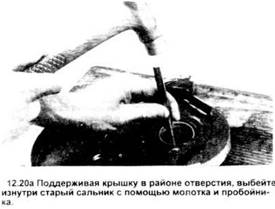
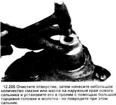
20. Replace the old seal in the cover with a new one (see figure).
21. Apply a thin coat of RTV sealant to both sides of the front cover gasket and position the gasket in the cover. Use a couple of bolts through the holes in the cover to press the gasket against the cover.
22. Attach the front cover with gasket to the engine. Screw in, but do not tighten, the cover support bolts.
23. Lubricate the contact surface of the pulley hub with moly grease and slide the pulley onto the crankshaft with one hand, while supporting the front cover with the other. Make sure that the key on the crankshaft is aligned with the corresponding groove in the pulley hub. If there is a slight misalignment, centering is achieved by passing the hub through the flange of the seal.
24. Tighten the front cover mounting bolts in a crisscross pattern in three steps.
25. Install the pulley bolt with washer and tighten it to the specified torque.
26. Install the oil pan.
The material was copied from an information website FORDBOOK