2. Place the drive shaft in a vice.
3. Mark the shaft and joint housing to ensure they are aligned during installation.
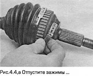
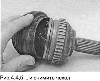
4. Note the position in which both clamps of the inner joint boot are installed. Release the clamps and pull the boot along the drive shaft (see Fig. 4.4, a, b).
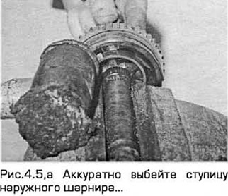
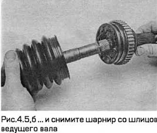
5. Carefully knock the outer joint hub out of the drive shaft splines using a copper drift or a copper-faced hammer. You will feel some resistance before the inner elastic rings come out of the groove. Be careful not to damage the bearing separator (see Fig. 4.5, a, b).
6. Remove the elastic ring from the end of the shaft (see Fig. 4.6).
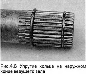
7. Pull the cover over the remaining ring and remove it together with the rings.
8. Clean the drive shaft and purchase a new hinge retaining ring. The boot clamps also need to be replaced.
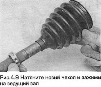
9. Pull the new boot over the inner elastic ring onto the drive shaft together with the new clamps (see Fig. 4.9).
10. Install the new outer elastic ring into the shaft groove.
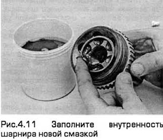
11. Remove the old grease. Fill the inside of the joint with new grease (approximately 100 g of constant velocity joint grease), see Fig. 4.11.
12. Install the joint on the splines of the drive shaft. Tap it so that the internal elastic rings snap into the groove.
13. Pull the boot along the shaft and install it on the joint and on the constant velocity joint housing. The small diameter end of the boot should fit into the groove on the drive shaft.
14. Check: the hinge should not be twisted or bent. Then insert a small screwdriver under the edge of the cover from the side of the case. This is necessary to release air when performing the next operation.
15. Remove the screwdriver, then install the clamps and tighten them.
[The original article is available on the website: www.FordBook.ru]