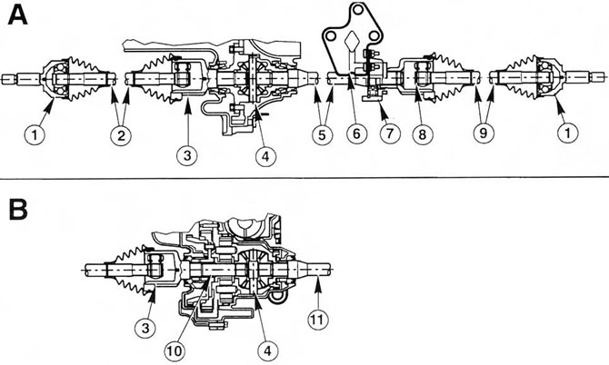
 Fig.1.1. Drive shafts - longitudinal section.
A Non-automatic transmission (MTX 75)
In Automatic transmission (CD4E)
1. External constant velocity joint
2. Left drive shaft
3. Inner joint of the left drive shaft (three-bearing roller joint)
4. Differential
5. Intermediate shaft
6. Intermediate shaft support bearing bracket
7. Intermediate shaft bearing
8. Inner joint of the right drive shaft (three-bearing roller joint)
9. Right drive shaft
10. Left differential output shaft (CD4E)
11. Intermediate shaft (CD4E)
2. Each drive shaft contains three main components: an inner joint (three-point roller joint), a shaft, and an outer constant velocity joint. The inner male end of the left three-point joint is fixed on the differential side by an elastic ring. The inner female end of the right drive shaft is fixed by an elastic ring on the intermediate shaft. The intermediate shaft rests on a bearing mounted in a bracket that is bolted to the rear of the cylinder block. The outer constant velocity joint (ball type) of each drive shaft is fixed to the hub by a nut.
[The original can be found on this resource FordBook.ru]