Withdrawal
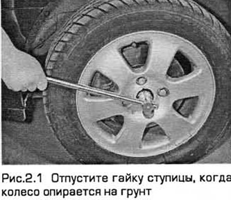
1. Remove the wheel cover. Apply the parking brake and engage first gear or set the selector to "R". Loosen the hub nut about half a turn. It is tightened with great effort (see fig.2.1).
2. Loosen the front wheel mounting nuts. Apply the parking brake, raise the front end and place it on stands. Remove the wheel.
4. Remove the front brake disc (chapter 9).
5. Completely unscrew and remove the hub/drive shaft mounting nut. Note that this nut can only be reinstalled a maximum of five times. It makes sense to put a small risk on it each time you remove it. Purchase a new nut if necessary.
6. While holding the suspension strut piston with a hex wrench, loosen the nut of its upper support, and then unscrew it five turns. It is not necessary to remove the nut, but note that a new one will be required during installation. Disconnect the ABS harness from the strut (in the presence of).
7. Turn away a nut of fastening of a connecting link of the stabilizer of cross-section stability to a rack of a forward suspension bracket. Move the link to the side.
8. Remove the cotter pin from the ball joint nut located at the end of the tie rod. Loosen the nut and remove the linkage from the knuckle arm using a ball joint puller. Be careful not to damage the ball joint seal.
9. Given which side the ball joint clamp bolt of the lower front suspension arm is installed, remove the bolt from the steering knuckle. Press the ball joint away from the steering knuckle. If this is difficult to do, carefully pry the clamp open with a power flat-tip screwdriver or similar. Be careful not to damage the ball joint seal.
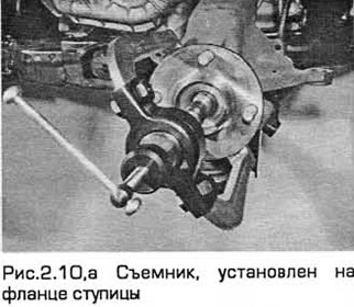
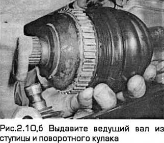
10. Using a universal puller installed on the hub flange, squeeze the drive shaft out of the hub and steering knuckle (see Fig. 2.10, a, b). After releasing the drive shaft, support it on a stand so that the inner joint does not rotate more than 18° (to prevent damage).
Left drive shaft
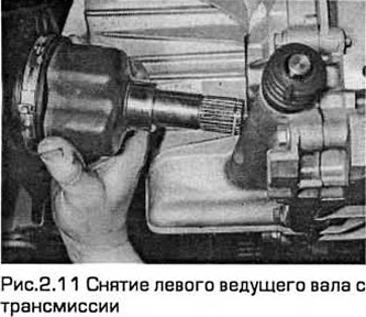
11. Insert a pry bar between the inner shaft joint and the transmission case, placing a thin piece of wood between the pry bar and the case. Press the inner joint away from the differential (see fig. 2.11). If this is difficult to do, tap the mount with your palm.
12. Be careful not to damage adjacent components and get ready to clean up oil spills.
13. Please note that (only on models with non-automatic transmission) when the right drive shaft is removed, the left drive shaft can be released with a fork end drift inserted from the right side. Be careful not to damage the differential gears.
14. Pull out a shaft from under the car.
15. Remove the elastic ring from the groove on the inner end of the shaft and purchase a new one.
Right drive shaft
16. The right drive shaft can be removed from the transmission along with the intermediate shaft, or it can be disconnected from the intermediate shaft. If you are disconnecting it from the intermediate shaft, then with a soft-faced hammer, sharply hit the body of the internal constant velocity joint, knocking it off the intermediate shaft. The inner elastic ring can be removed and the drive shaft can be pulled out of the splines.
17. Remove the elastic ring from the groove on the outer end of the intermediate shaft and purchase a new one.
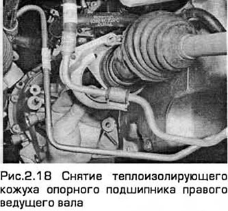
18. If you remove the entire right drive shaft assembly, then proceed as follows. Turn out bolts of fastening of an arm of the basic bearing of a shaft from the block of cylinders, from its back party and remove the heat-insulating casing (see fig.2.18).
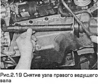
19. Remove the shaft assembly from the transmission and bearing bracket and remove it from under the vehicle (see fig.2.19). Get ready to clean up oil leaks.
Both shafts
20. Check the condition of the transmission seals and replace them if necessary (chapter 7A). Inspect the thrust bearing and replace if necessary (paragraph 13).
Installation
Right drive shaft
21. If the intermediate shaft is not removed, go to step 24. If it is removed, follow the instructions below.
22. Carefully install the driveshaft assembly into the support bearing and into the transmission so as not to damage the collar. By turning the shaft, put it on the differential splines.
23. Torque tighten the support bearing mounting bolts to the bracket mounted on the cylinder block. Go to step 29.
24. Install a new elastic ring in the groove on the outer end of the intermediate shaft. Then apply 6-8 g of grease (Ford SQM1C-9004-A) on the splined part of the intermediate shaft along its circumference. This prevents frictional corrosion.
25. Install the right drive shaft on the intermediate shaft splines and push the drive shaft until the inner elastic ring snaps into the groove of the shaft. (It will be heard.).
Left drive shaft
26. Install a new elastic ring in the groove on the inner end of the input shaft.
27. Be careful not to damage the differential boot when inserting the shaft.
28. Insert the drive shaft into the transmission so that the elastic ring snaps into place.
Both shafts
29. Pull the steering knuckle out and insert the outer end of the drive shaft into the hub. While turning the shaft, insert it into the splines of the hub and press it completely into it. Ford recommends a special tool for this operation, but the splines are unlikely to be tight. If this happens, then you will have to use such a device or make something similar.
30. Screw the nut onto the hub by hand.
31. Install the ball joint limit switch of the lower front suspension arm into the steering knuckle from below. Insert the clamp bolt into its original position. Screw on the nut and tighten it to the required torque.
32. Install the ball joint of the tie rod end switch on the steering knuckle and tighten the nut. Tighten it to the required torque.
33. The cotter pin holes on the ball joint nut must be aligned. If necessary, the nut can be slightly tightened to align the holes, but the tightening torque must be within tolerance for the required torque. Insert a new cotter pin and straighten it.
34. Install the anti-roll bar link to the front suspension strut and tighten the nut to the specified torque.
35. Turn away a nut of the top support of a rack of a suspension bracket and replace it with a new nut, tightening the demanded moment (chapter 10). Install the ABS harness to the strut bracket (in the presence of).
36. Install the front brake disc (chapter 9).
37. Check the transmission oil level and top up if necessary (Chapter 1).
38. Install the wheel and lower the car to the ground. Tighten the wheel nuts to the required torque.
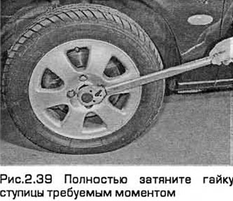
39. Fully tighten the hub nut to the correct torque (see fig.2.39). Then install the wheel cover.
Visitor comments