Replacement without removing the drive shaft
2. Loosen the front wheel mounting nuts. Apply the parking brake, raise the front end and place it on stands. Remove the wheel.
3. Turn away a nut of fastening of a connecting link of the stabilizer of cross-section stability to a rack of a forward suspension bracket. Move the link to the side.
4. Remove the cotter pin from the ball joint nut located at the end of the tie rod. Loosen the nut and remove the linkage from the knuckle arm using a ball joint puller. Be careful not to damage the ball joint seal.
5. Given which side the ball joint clamp bolt of the lower front suspension arm is installed, remove the bolt from the steering knuckle. Press the ball joint away from the steering knuckle. If this is difficult to do, carefully pry the clamp open with a power flat-tip screwdriver or similar. Be careful not to damage the ball joint seal.
6. Mark the shaft and pivot housing to align when installed.
7. Note the position in which both clips of the inner hinge boot are installed. Release the clips and pull the cover over the drive shaft away from the transmission.
8. When removing the hinge from its body, pull the front suspension strut (outside). After removing the hinge from the housing, the bearing rollers may pop out. Mark them for subsequent installation in their places with a drop of paint. Support the inner end of the drive shaft on a stand.
9. Remove the support ring from the pivot housing.
10. Remove the remaining bearing rollers from the hinge and mark them with paint so that they can be installed later in their places.
11. The inner end of the drive shaft and the splined hub of the joint must be marked for alignment. If there are no marks, apply them (drip paint).
12. Remove the elastic ring that secures the hinge to the shaft.
13. Using a puller, remove the pivot from the end of the input shaft and remove the cover from it.
14. If you need to remove the outer hinge, see paragraph 4.
15. Clean the drive shaft and purchase a new pivot retainer ring. Boot clips and tie rod end pin also need to be replaced.
16. Pull a new cover on a drive shaft together with new clips. Also install the support ring on the hinge body.
17. Establish the hinge on splines of a leading shaft. If necessary, tap it with a soft-faced hammer to set it in place. Slide the hinge with a lead-in chamfer on the end of the shaft and aligning the marks made during removal. Lock it in place with a new elastic ring so that it snaps into place in the groove.
18. Install the bearing rollers in their places on the hinge. Use grease to hold the rollers.
19. Pulling the front suspension strut outward, insert the hinge into its body, aligning the marks made during removal. Fill the inside of the joint with grease (approx. 180 g CV joint grease).
20. Pull the boot along the shaft and install it on the support ring located on the hinge housing. The end of the small diameter boot should fit into the groove on the drive shaft.
21. Check that the hinge must not be twisted or bent. Then insert a small screwdriver under the edge of the cover from the side of the case. This is necessary to allow air to escape during the next operation.
22. Press the hinge completely into its body, and then pull it out 20 mm from there. Pull out the screwdriver, and then install the latches and secure them.
23. Install the front suspension lower arm ball joint to the steering knuckle assembly. Install and tighten the clamp nut and bolt.
24. Install the ball joint of the tie rod end switch on the steering knuckle and tighten the nut. Tighten it to the required torque. The cotter pin holes on the ball joint nut must be aligned. If necessary, the nut can be slightly tightened to align the holes, but the tightening torque must be within tolerance for the required torque. Insert a new cotter pin and straighten it.
25. Install the anti-roll bar link to the front suspension strut and tighten the nut to the specified torque.
26. Install the wheel and lower the car to the ground. Tighten the wheel nuts to the required torque.
Replacement after removal of the input shaft
27. Install the drive shaft in a vise.
28. Mark the shaft and pivot housing to align when installed.
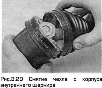
29. Consider the position in which both clips of the inner hinge boot are installed. Release the clips and pull the boot over the drive shaft (see fig. 3.29).
30. Remove the hinge from its body. After removing the hinge from the housing, the bearing rollers may pop out. Mark them for subsequent installation in their places with a drop of paint.
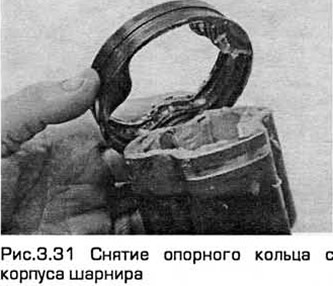
31. Remove the support ring from the hinge housing (see fig. 3.31).
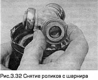
32. Remove the remaining bearing rollers from the hinge and mark them with paint to install later in their places (see fig. 3.32).
33. The inner end of the drive shaft and the splined hub of the hinge must be marked for alignment. If there are no marks, apply them (drip paint).
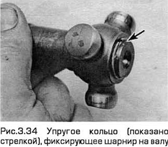
34. Remove the elastic ring that fixes the hinge on the shaft (see fig. 3.34).
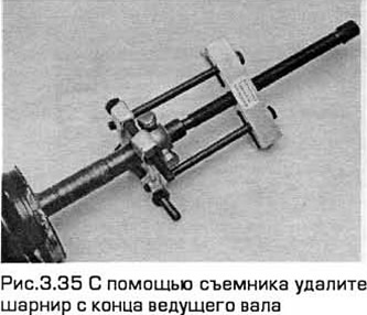
35. Using a puller, remove the hinge from the end of the drive shaft and pull off the cover from it (see fig.3.35).
36. If you need to remove the outer hinge, see paragraph 12.
37. Clean the drive shaft and purchase a new pivot retainer ring. The case clips also need to be replaced.
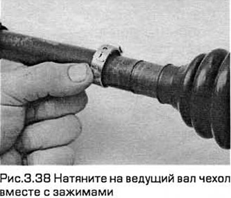
38. Pull the new boot over the drive shaft along with the new clamps (see fig.3.38).
39. Also install the support ring on the hinge body.
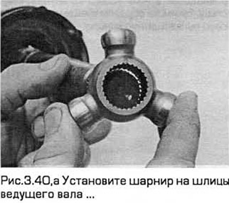
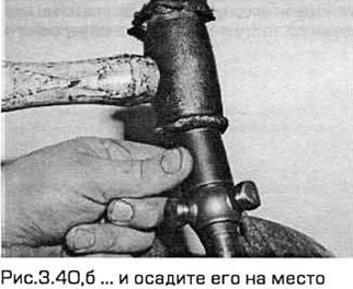
40. Install the hinge on the splines of the input shaft. If necessary, tap it with a soft-faced hammer to set it in place. Put on the hinge with a lead-in chamfer on the end of the shaft and aligning the marks made during removal. Lock it in place with a new elastic ring so that it snaps into the groove (see Fig. 3.40, a, b).
41. Install the bearing rollers in their places on the hinge. Use grease to hold the rollers.
42. Insert the hinge into its body, aligning the marks made during removal. Fill the inside of the joint with grease (approx. 180 g CV joint grease).
43. Pull the boot along the shaft and install it on the support ring located on the hinge housing. The end of the small diameter boot should fit into the groove on the drive shaft.
44. Check: the hinge must not be twisted or bent. Then insert a small screwdriver under the edge of the cover from the side of the case. This is necessary to allow air to escape during the next operation.
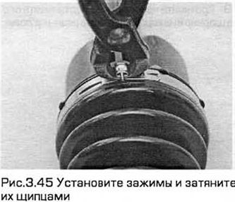
45. Press the hinge completely into its body, and then pull it out 20 mm from there. Pull out the screwdriver and then install the clips and tighten them (see fig.3.45).
Visitor comments