Note: If the CV joint is worn out and requires major repairs (usually due to torn boots), then study all instructions before starting the repair.
Preparation
1. Remove the axle drive (section 8).
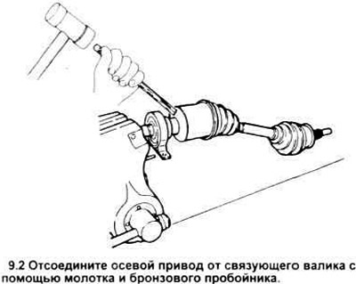
2. With the right axle drive removed on vehicles with a manual or 3-speed automatic transmission, place the connecting shaft in a vice with a wooden spacer. Disconnect the axle drive from the connecting roller by knocking it out with a bronze punch (see figure). Do not let the axle drive fall to the floor after it comes out.
3. Place the axle drive in a vice with a wooden lining to prevent crushing the shaft.
Inner CV joint and boot
Disassembly
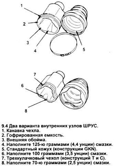
4. Note: There are two types of CV joint inner assemblies (see picture). Although they are similar in design, their parts are not interchangeable. The repair procedure is the same for both. Cut off the boot seal retaining clips and slide the boot toward the center of the axle drive. Mark the tee housing and axle drive so that they can be returned to their original position, then pull them off the hub.
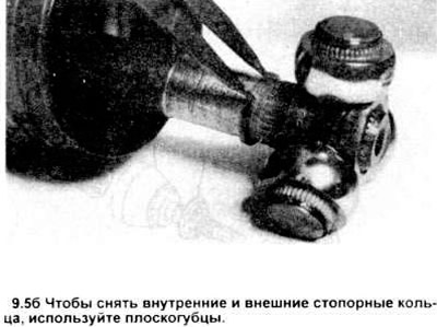
5. Mark the hub assembly and shaft. Remove the hub assembly from the axle by first removing the inner snap ring and pulling the hub back to release the outer snap ring. Remove the outer snap ring, pull the assembly off the axle drive (see pictures).
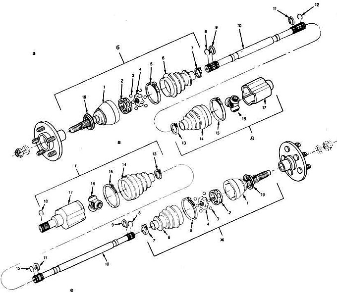
9.5, a. Three-dimensional image of axial drive elements.
a. axle shaft - disassembled view.
b. outer CV joint unit
v. left axle shaft
g. inner CV joint unit
d. inner CV joint unit.
i.e. right axle shaft.
f. outer CV joint unit.
Note: When replacing a boot, CV joint, intermediate shaft or complete axle assembly, check the transmission type, gear ratio, engine size and determine whether it is left or right side, outer or inner end.
1. Outer ring of the outer unit and shortened shaft.
2. Ball holder.
3. Balls (6 pieces).
4. Inner race of the outer unit.
5. Cover clamp (large).
6. Cover.
7. Case clamp (small).
8. Spring ring.
9. Retaining ring.
10. Intermediate shaft.
11. Retaining ring.
12. Spring ring.
13. Case clamp (small).
14. Cover.
15. Cover clamp (large).
16. Internal triple hinge assembly.
17. Inner assembly of the inner race and shortened roller.
18. Spring ring.
19. Anther.
6. Wrap the hub bearings with tape or a rag to secure them during assembly and disassembly.
7. Remove the hub assembly from the axle.
8. Pull the cover off the axle.
Examination
9. Clean the grease from the hub and its housing. Carefully disassemble the hub assembly, removing one piece at a time, wash the needle bearings with solvent. Check the rollers, hub cross, bearings and housing for scratches, pitting and other signs of increased wear that may affect the replacement of the inner CV joint.
Assembly
10. Apply a coat of special grease to the inside surfaces of the bearings to hold them in place when assembling the hub unit. Pack the housing with grease equal to half the capacity of the new boot, and leave the rest in the boot.
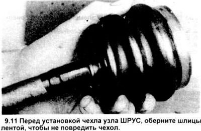
11. Wrap tape around the splines of the axle drive to prevent damage to the boot, then place the boot on the axle (see illustration).
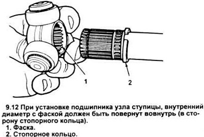
12. Install the hub bearing so that the chamfer is opposite the retaining ring (see figure).
13. Install a new snap ring onto the end of the shaft, place the hub bearing opposite the ring and install the snap ring into the groove.
14. Install the triple joint housing.
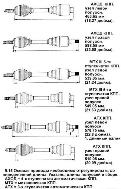
15. Insert the boot into the housing and axle sealing grooves, then adjust the axle length to normal (see figure).
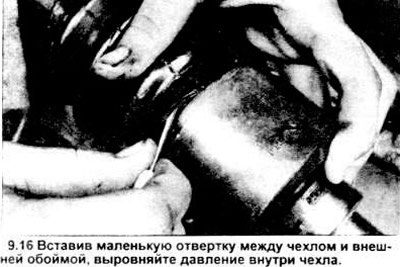
16. After adjusting the length of the axis, equalize the pressure in the cover by inserting a screwdriver between the cover and the body (see figure). Do not damage the cover with the tool.
17. Install the casing clamps. Use special pliers to tighten the clamps.
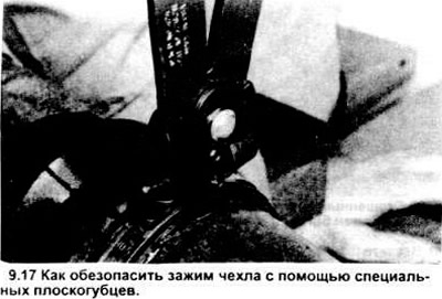
Caution: Use only low profile clamps on inner CV joints.
18. Connect the axle drive to the connecting shaft (only the right side on all manual and 3-speed automatic transmissions).
19. Install the axle drive (or drive unit with connecting shaft) as described in section 8. Don't forget to install a new snap ring on the inner short axle.
Outer CV joint and cover
Disassembly
20. Follow paragraphs 2 and 3 in this section.
21. Cut off the boot retaining clips and remove it from the outer race. Using a bronze drift in the inner race, free the CV joint assembly from the axle (see figure). Considerable force will be required as the inner race will have to overcome the resistance of the axle shaft. Do not allow the CV joint assembly to fall.
22. Place the outer assembly in a vice using wooden spacers.
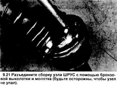
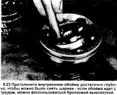
23. Press the inner race down enough to remove the ball bearing. If it is difficult to tilt, knock out the inner race with a hammer through a bronze drift (see figure).
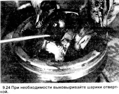
24. Remove the balls from the separator one by one using a flat-head screwdriver (with a rounded end) or a wooden tool (see figure).
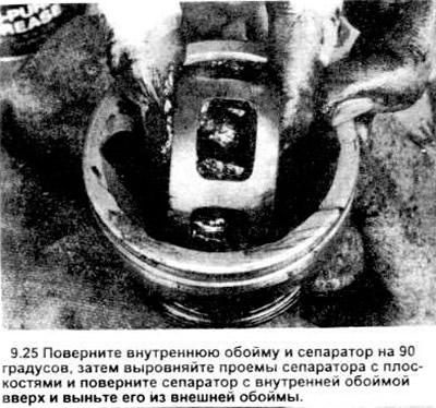
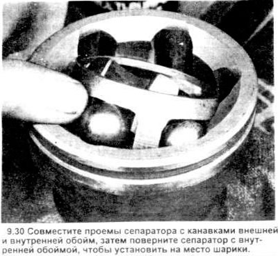
25. After removing all the balls from the separator and turning the separator inner race by 90 degrees, align the openings of the separator with the planes of the outer race and pull the assembly out of the outer race (see figure).
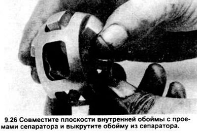
26. Remove the inner race from the separator by turning it 90 degrees in the separator, aligning its planes with the openings in the separator and unscrewing the inner race from the separator (see figure).
Examination
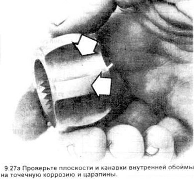
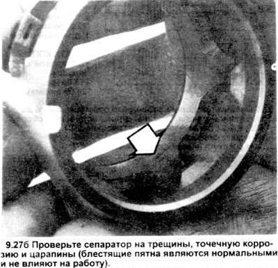
27. Clean the components with solvent to remove all traces of grease. Check the separator and races for pitting, scratches, cracks and other signs of wear and damage. Shiny, polished spots are normal and will not affect the operation of the CV joint (see pictures).
Assembly
28. Install the inner race into the separator in the reverse order given in paragraph 25.
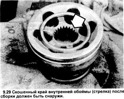
29. Install the separator unit with the inner race in the reverse order of disassembly (paragraph 25). The beveled edge of the splined part of the inner race should "look" outward after installation in the outer race (see figure).
30. Press the balls into the windows (openings) of the separator (see figure).
31. Fill the CV joint with grease through the inner spline hole. Press the grease into the bearing - insert a wooden pin into the spline hole and push it toward the bottom of the unit. Repeat the procedure until the bearing is completely filled with grease (see figure).

32. Place the boot on the axle shaft as described in paragraph 11. Apply some grease inside the axle boot.
33.Install a new snap ring and position it in the groove of the axle shaft.
34. Install a new snap ring onto the end of the axle shaft.
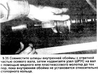
35. Place the CV joint assembly on the axle shaft, aligning the splines. Using a hammer with a copper or plastic pad, push the CV joint assembly onto the axle shaft until it stops against the retaining ring (see figure).
36. Adjust the length of the axial drive and put on the cover. See paragraphs 16-17.
37. Assemble the axle drive unit with the connecting shaft (right side only and only in 3-speed automatic transmissions).
38. Install the axle drive as described in section 8.