Warning: If any steering fastener becomes loose or is lost, replace it with a new one immediately and discard the used ones and do not reuse them.
Caution: If the right and left axle drives are removed at the same time, the axle gears must be supported so that they do not fall into the housing (manual and 3-speed automatic transmissions only). Wooden dowels 23 8 mm (15/16 in) in diameter are suitable for this purpose, which are inserted into each axle gear. If this is not done and the gear falls, the differential must be removed from the transmission to align the gears. This procedure requires a special puller and an adapter to install the drive in the hub due to the specific fit of the outer splines of the axle and the inner splines of the hub.
Removal
Note: The information applies to the right axle drive of vehicles with a 3-speed automatic transmission and both drives on a manual transmission or 4-speed automatic transmission.
1. Loosen the wheel hub nut, raise the vehicle, and securely support it on stands. Remove the wheel(s).
2. Remove the brake caliper and brake disc as described in chapter 9.
3. Unscrew the hub stopper (axle nut) from the axle (if you have a 3-speed automatic transmission and need to remove both axle drives, then start with the right one).
Place a lever between the two wheel studs to prevent the hub from turning when the nut is loosened.
4. Unscrew the bolt securing the bracket supporting the brake hose to the strut.
5. Unscrew the bolt securing the lower suspension arm to the steering knuckle and separate the arm from the knuckle (see chapter 10).
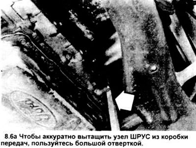
6. Using a large screwdriver or pry bar, pry the inner CV joint assembly out of the transmission (see illustration). On 3-speed automatic and 3-speed manual (right side only), unscrew the shaft support bearing from the bracket (see illustration). Pull the shaft out of the transmission. Be careful not to damage the housing or oil pan. Suspend the axle with wire - do not let it hang over the outer CV joint, otherwise it will damage it.
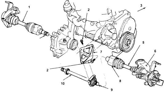
8.6, b. Mounting parts of the axial drive and connecting roller (only manual and 3-speed automatic transmission).
Note: MTX is shown. FLC is similar.
1. Left axle shaft assembly.
2. Bolt.
3. Front of the car.
5. Right axle shaft assembly.
6. Outer CV joint.
7. Bracket.
8. Inner CV joint.
9. Latch ring.
10. Bonding roller.
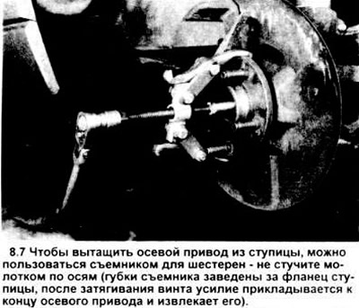
7. Using a gear puller, remove the axle drive from the hub (see figure).
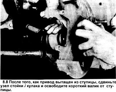
8. Once the axle drive is removed from the hub splines, slide the strut/knuckle assembly out and lift the outer CV joint out of the hub. Remove the support wire and carefully remove the axle drive from the vehicle (or shaft/axle drive assembly) (see illustration).
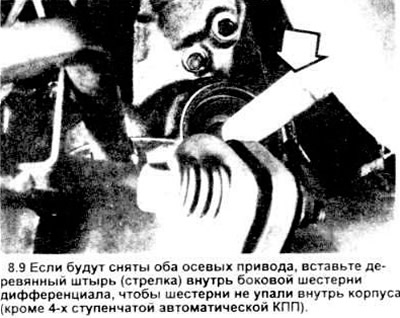
9. If both axle drives are removed, insert a tight-fitting wooden dowel (15/16" diameter) into the differential side gear on the right side (not necessary for 4-speed transmissions) (see illustration); then repeat the operations described in paragraphs 1 through 8 to remove the left axle drive. For the left side gear, also install the support.
Left axle drive on vehicles with 3-speed automatic transmission
10. Remove the right drive as described above.
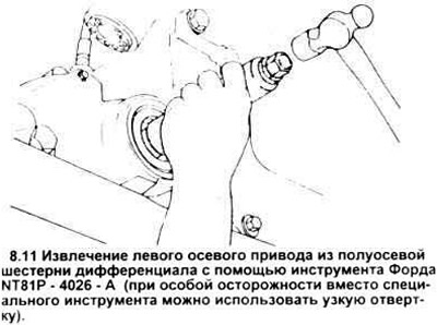
11. Using the Ford T81P-4026A tool or a narrow screwdriver inserted through the right differential side gear, pry the left drive short shaft out of the left side gear just enough to remove the snap ring on the short shaft from the side gear (see illustration). Insert a wooden dowel (15/16 inch diameter) into the right differential side gear to prevent it from falling out when the left drive short shaft is removed.
12. When removing the left axle drive from the vehicle, follow the procedures described in paragraphs 7 and 8.
Note: Be sure to insert the wooden dowel into the left axle gear.
Installation (both drives)
Note: If both actuators have been removed, install them one at a time, removing the wooden dowel from each side once the actuator is ready to be installed in the transmission (manual and 3-speed automatic transmissions only).
13. Install the new snap ring onto the internal splines of the short shaft.
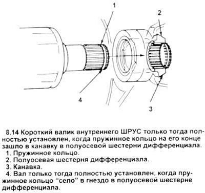
14. Apply a coat of multi-purpose grease to the differential seals and insert the short inner CV joint shaft or the tie shaft (right side only, manual or 3-speed automatic transmission) into the differential side gear until the shaft is fully seated and the spring ring snaps into place (see illustration).
15. Insert the short CV shaft through the strut/knuckle assembly and install it into the hub (make sure the splines are aligned properly). Manually push the shaft into the hub as far as you can.
16. Bolt the link roller support bearing to the bracket and tighten the bolts to the torque specified in the specification (manual and 3-speed automatic transmission only).
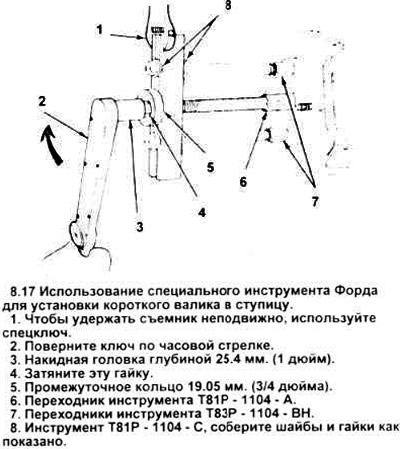
17. Using Ford tool T81P - 1104 - With adapters T83P - 1104 - BN and T81P - 1104 - A, push the short shaft into the hub until it snaps into place (see picture), then proceed to paragraph 24.
18. Remove the tool and install the axle washer and new nut. Tighten the nut to the specified torque and to prevent the hub from turning, place a screwdriver between the two wheel studs.
19. Lower the lower control arm and insert the ball joint stud into the knuckle. Install a new tie rod bolt and tighten it to the specified torque (chapter 10).
20. Install the brake disc and caliper (chapter 9).
21. Install the brake hose support bracket bolt.
22. Hang the wheel, screw on the nuts, lower the car. Tighten the nuts to the required tightening torque.