NOTE: The left and right front wheel drives differ in design (the right front wheel drive is made as one piece with the intermediate shaft), therefore the left and right drives are partially removed using different techniques, described separately for each drive.
You will need: all the tools to remove the engine crankcase protection (see Removing and installing mudguard and engine crankcase protection), disconnecting the ball joint from the steering knuckle (see Replacing the ball joint), steering rod from the steering arm (see Replacing the Outer Tie Rod End), as well as a socket head and a 13 mm wrench, a lug wrench.
For removal left front wheel driveperform the following operations.
1. Remove the engine crankcase guard (see Removing and installing mudguard and engine crankcase protection).
2. Drain the oil (working fluid) from the gearbox (see Changing the oil in a manual transmission or the working fluid in an automatic transmission).
3. Remove the decorative cap of the left front wheel, if present.
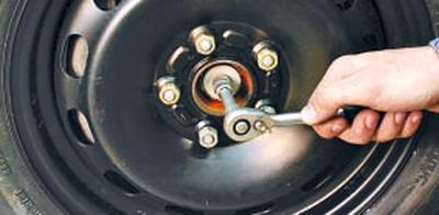
4. Loosen the hub bolt and wheel nuts.
NOTE: If your vehicle has alloy wheels, remove the wheel as the hub covers the vehicle's hub bolt.
WARNING: Loosen and tighten the wheel nuts only with the vehicle on the ground.
5. Apply the parking brake, place chocks under the rear wheels and raise the front of the car using reliable supports.
6. Remove the front wheel if the wheel has a stamped disc and has not been removed beforehand.
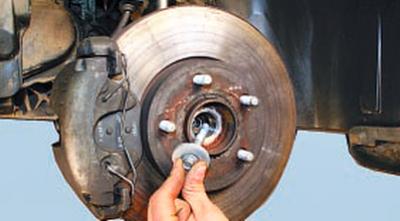
7. Unscrew the hub bolt and remove it together with the thrust washer.
8. Disconnect the left steering rod from the steering arm (see Replacing the Outer Tie Rod End).
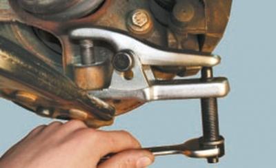
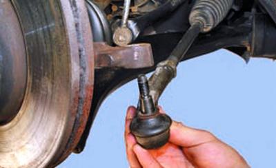
9. Unscrew the ball joint pin nut and press out the pin using a puller (see Replacing the ball joint).
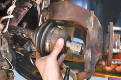
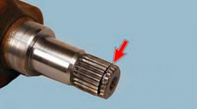
10. Move the shock absorber strut slightly to the side and remove the outer constant velocity joint tailpiece from the hub.
NOTE: The front brake caliper has been removed for clarity. It is not necessary to remove it when removing the front wheel drive.
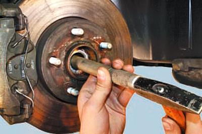
HELPFUL TIP: If you cannot remove the joint tailstock by hand, knock it out of the hub using light hammer blows through a soft metal punch.
CAUTION: Be careful not to allow the drive shaft to come out of the inner joint housing as this may cause damage to the joint.
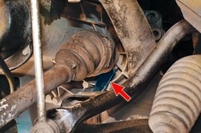
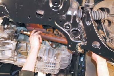
11. Having rested the mounting blade against the gearbox housing…
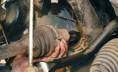
12….press out the inner drive joint from the axle gear and remove the left front wheel drive assembly.
NOTE: The gap between the inner joint housing and the gearbox housing is very small, it is impossible to insert the end of the mounting blade into it completely at once. After inserting the pointed part of the mounting blade into the gap, carefully hammer the end along the blade to drive it deep into the gap and use it to push the joint housing away from the housing like a wedge until the joint tailstock retaining ring comes out of the axle shaft gear. Then use the blade to finally push the joint tailstock out of the gear.
CAUTION: When using a tire iron to press the inner joint out of the transmission axle gear, be careful not to damage the transmission case or joint.
Replace the inner joint tailstock snap ring with a new one each time the drive is removed from the vehicle.
13. To install the drive, first insert the splined tail of the outer joint housing into the wheel hub, install the thrust washer and screw in the hub bolt until it stops, without tightening it completely.
14. Then insert the splined tailpiece of the inner joint housing into the axle shaft seal and turn the drive shaft slightly so that the splines of the joint tailpiece and the axle shaft gear align.
15. Move the front suspension arm down and, using a sharp movement of the shock absorber strut with the steering knuckle, press the drive into the axle shaft gear until the drive is secured with a retaining ring.
16. Try to pull the inner joint tailpiece out of the axle gear by giving the steering knuckle a sharp tug. If you succeed, repeat the installation of the joint into the gear. If the second attempt does not produce the desired result, replace the inner joint tailpiece retaining ring.
17. After installing all the parts, fill the gearbox with oil (working fluid) (see Changing the oil in a manual transmission or the working fluid in an automatic transmission).
18. Install the wheel (if its disk is stamped) and tighten the wheel mounting nuts until they stop, without tightening them completely.
19. Place the vehicle on its wheels, removing it from the supports, and tighten the hub bolt.
WARNING: Tighten the hub bolt to 35 N·m (3.5 kgf·m) with the vehicle on the ground and then turn it 90° further. Never move the vehicle with the hub bolt loose to avoid damaging the hub bearing cage.
NOTE: If the vehicle is equipped with alloy wheels, the hub bolt will need to be tightened before the wheel can be installed on the raised vehicle. To prevent the hub from turning, engage first gear in the transmission and have an assistant press and hold the brake pedal.
20. Tighten the wheel nuts.
For removal right front wheel drive perform the following operations.
1. Perform on the right side of the vehicle steps 1–10 as performed on the left side to remove the left front wheel drive (see XXXXXXXXXX above).
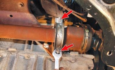
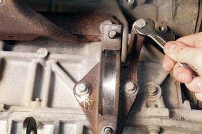
2. Unscrew the two nuts securing the intermediate support bracket…
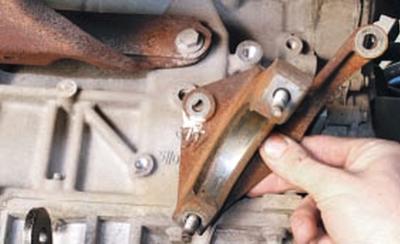
3….and remove the bracket.
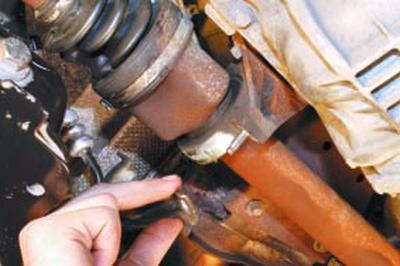
4. Remove the inner joint shank from the axle gear…
5….and remove the right front wheel drive assembly.
NOTE: If necessary, remove the three bolts securing the intermediate support bracket to the engine block…
…and remove the bracket.
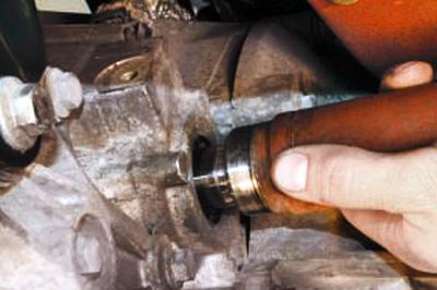
6. To install the drive, first insert the splined shank of the outer joint housing into the wheel hub, install the thrust washer and screw in the hub bolt until it stops, without tightening it completely.
7. Then insert the splined tailpiece of the inner joint housing into the axle shaft seal and turn the drive shaft slightly so that the splines of the joint tailpiece and the axle shaft gear align, then move the shock absorber strut with the steering knuckle to insert the drive into the axle shaft gear until it stops.
8. Install and secure the intermediate support bracket with nuts.
9. After installing all the parts, fill the gearbox with oil (liquid) (see Changing the oil in a manual transmission or the working fluid in an automatic transmission).
10. Install the wheel and tighten the nuts until they stop, without tightening them completely.
11. Place the vehicle on its wheels, removing it from the supports, and tighten the hub bolt.
WARNING: Tighten the hub bolt to 35 N·m (3.5 kgf·m) with the vehicle on the ground and then turn it 90° further. Never move the vehicle with the hub bolt loose to avoid damaging the hub bearing cage.
12. Tighten the wheel nuts.
(The text was obtained in its entirety from the specified website: FordBook.ru)