Examination
When checking, the cylinder block and crankshaft must be clean. Turn the engine over with the crankshaft facing up.
Unscrew the main bearing cap mounting bolts and remove the caps. Arrange the caps in the appropriate order.
Remove the main bearings from the cylinder block and bearing caps. Wipe the main bearings thoroughly.
Checking the main bearing clearance
HCS and Endura-E engines
Wipe the outside of the bearings and their mounting locations in the cylinder block and caps. Insert the dry upper bearings into the cylinder block. Note that the upper bearings have grooves. Check that the projection on each bearing fits into the groove in the cylinder block.
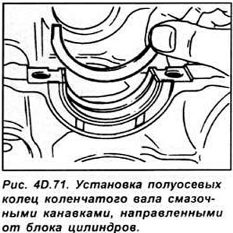
Install the crankshaft axle ring into the cylinder block so that the lubrication grooves are directed away from the cylinder block (see Fig. 4D.71).
CVH and PTE engines
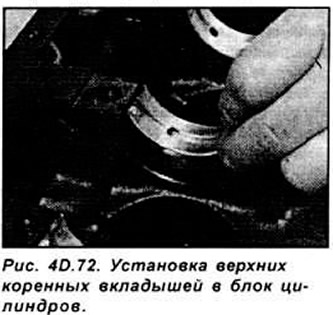
Wipe the outside of the main bearings and insert the upper bearings into the cylinder block. Note that with the exception of the front bearing, the upper bearings have grooves. Check that the lug on each bearing fits into the groove in the cylinder block (see Fig. 4D.72).
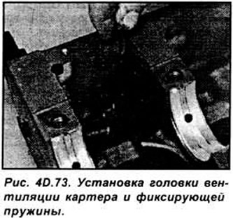
Install the crankcase ventilation head and retaining spring into place in the cylinder block (see Fig. 4D.73).
Install the crankshaft axle rings in place so that their oil grooves are directed away from the engine block.
Zetec and Zetec-E engines.
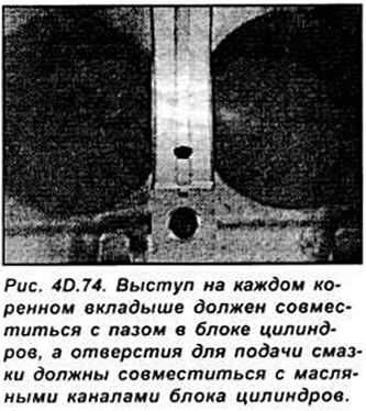
Wipe the outside of the main bearings and install them in the cylinder block. Install the axle rings on the central bearing. Check that the protrusion on each bearing fits into the cutout in the cylinder block (see Fig. 4D.74).
All engines
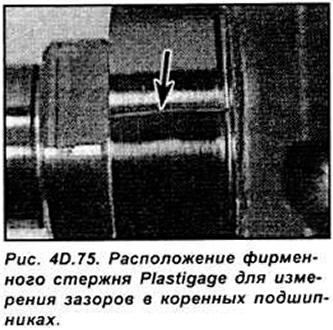
Thoroughly clean the bearing surfaces and crankshaft journals. Place a length of Plastigage measuring rod along each crankshaft journal (see Fig. 40.75).
Clean the working surfaces of the lower main bearings and install them on the crankshaft. Install the main bearing caps. Do not move the measuring rods.
Tighten the main bearing cap bolts to the specified torque. Do not rotate the crankshaft while measuring the main bearing clearances.
Unscrew the main bearing cap mounting bolts and remove them.
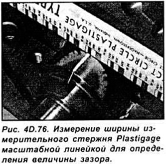
Measure the width of the Plastigage measuring rod with a scale that indicates the clearance size in each main bearing (see Fig. 4D.76).
Carefully clean all traces of the dipstick from the crankshaft journals and main bearings.
Installing the crankshaft
Remove the crankshaft from the cylinder block. Clean the working surfaces of the main bearings and lubricate them with a thin layer of motor oil. Also lubricate the working surface of the crankshaft axle ring.
Lubricate the crankshaft journals that operate in contact with the oil seal.
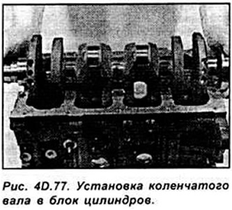
Install the crankshaft in the cylinder block. Clean the working surfaces of the lower main bearing shells, then lubricate them with a thin layer of engine oil and install them on the crankshaft. Install the main bearing caps in accordance with the identification marks. The arrows on the main bearing caps must point toward the valve timing drive (see Fig. 4D.77).
Tighten the main bearing cap bolts gradually and evenly from the center to the edge to the required torque.
Turn the crankshaft by hand. The crankshaft should rotate easily and evenly.
Check the crankshaft axial play. Install the left crankshaft oil seal cover.
(The original article is posted at: Fordbook.ru)