Contents: Removal ↳ Examination ↳
Removal
HCS and Endura-E engines
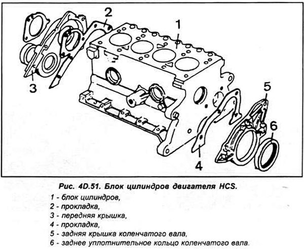
Remove the cylinder head and oil pan. Remove the oil pickup pipe and strainer.
Temporarily install the crankshaft pulley so that the crankshaft can rotate. Check the lower connecting rod cap and connecting rod for markings. If there are no markings, they must be applied in order to install the pistons with connecting rods in their places and in the correct position.
CVH and PTE engines
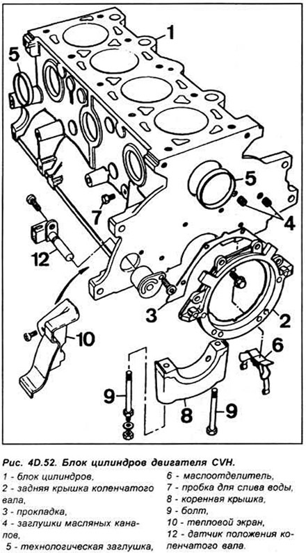
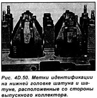
Remove the cylinder head, oil pan, oil pick-up pipe and strainer. Temporarily install the crankshaft pulley so that the crankshaft can be turned. Check the identification numbers, which should be stamped on the connecting rod ends on the exhaust manifold side.
Zetec and Zetec-E engines
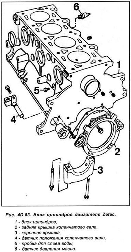
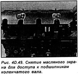
Remove the cylinder head and oil pan. Unscrew the screws securing the oil inlet pipe with the mesh filter to the oil pump, then unscrew the 4 nuts and remove the oil screen (see Fig. 40.49).
Temporarily install the crankshaft pulley so that it can be turned.
Check that the connecting rods and the lower connecting rod cap have identification numbers. The numbers are visible from the exhaust manifold side of the engine. In addition, each piston has an arrow pointing to the toothed belt drive. If there are no identification marks, apply them (see Fig. 4D.50).
All engines
Using your finger, check to see if there is a ridge (step) at the top of the cylinder.
Gradually unscrew the connecting rod lower cover mounting bolts by half a turn each time, unscrew the bolts. Remove the connecting rod lower cover.
Using a wooden hammer handle, push the piston and connecting rod out of the cylinder.
Repeat the operation of removing the pistons with connecting rods on the remaining cylinders.
After removing the pistons with connecting rods, reinstall the connecting rod lower head caps on them.
Examination
Clean the pistons and connecting rods thoroughly.
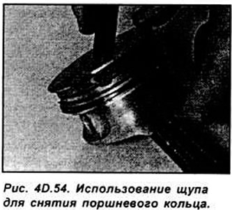
Remove the piston rings from the pistons by carefully sliding them toward the top of the piston so as not to scratch the aluminum alloy. Never slide them toward the piston skirt. Piston rings can easily be damaged if removed carelessly. Therefore, this operation must be performed with extreme caution. You can use old feeler gauges. Lift one edge of the piston ring that needs to be removed from the groove and insert the feeler gauge under it. Slowly move the feeler gauge around the piston and when the ring comes out of its groove, remove it upwards, with the feeler gauge preventing it from slipping into an empty groove, if there is one (see Fig. 4D.54).
Clean all traces of carbon from the top of the piston.
Clean the piston ring grooves in the piston using a piece of an old piston ring.
Using solvent, clean the pistons and connecting rods and wipe them dry.
Carefully inspect each piston for cracks around the skirt and piston pin holes.
If the piston skirt is worn out, the engine may have overheated. In this case, it is necessary to check the operation of the cooling and lubrication systems. Traces of carbon deposits on the side surface of the pistons indicate that there was a gas breakthrough. Burning of the head in the piston or burnt areas along the edge of the piston head indicate that the fuel combustion occurred with detonation or explosion, which was a consequence of incorrectly setting the ignition angle.
Piston pitting indicates that coolant has entered the combustion chamber. This could be due to a blown engine gasket.
Check the piston pin clearances and ease of movement by turning the connecting rod and piston in different directions.
Do not attempt to separate the pistons from the connecting rods. This work must be performed at a service station.
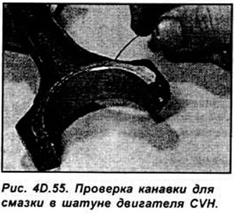
Inspect the connecting rods for cracks or other damage. On CVH engines, the connecting rods should have a clean oil groove at the base of the rod.