HCS and Endura-E engines
The valves must be removed from the valve of the first cylinder, which is located closest to the timing drive system.
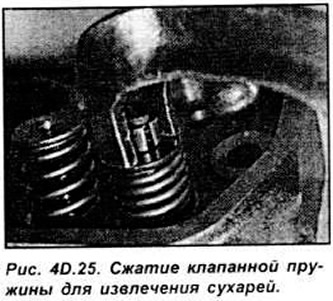
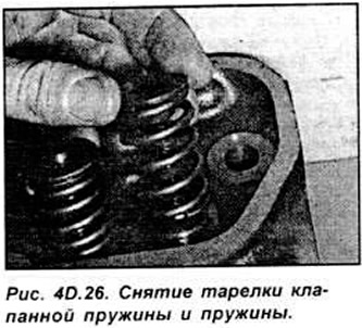
Compress the valve spring with a special tool and remove the crackers securing the upper spring retaining plate. Remove the upper plate and the valve spring, paying attention not to damage the valve stem (see Fig. 40.25-4D.27).
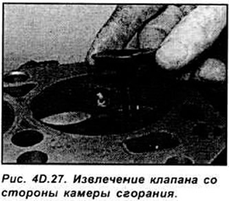
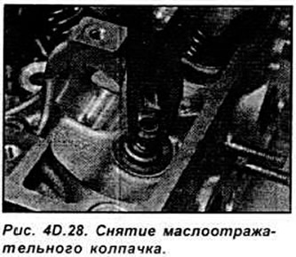
Remove the valve from the combustion chamber side of the head. Use a lever or pliers to remove the oil-deflecting cap.
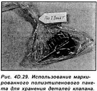
Repeat the operation to remove the remaining seven valves. Place the parts of each valve assembly in separate plastic bags so that they can be reinstalled during assembly (see Fig. 40.29).
CVH and PTE engines
Remove the camshaft, valve levers and hydraulic lifters.
Removal of the valves should begin with the valves of the first cylinder, located near the toothed drive belt.
Compress the valve spring with a special tool and remove the crackers of the upper spring retaining plate. Remove the upper plate and the valve spring, paying attention not to damage the valve stem.
Using a screwdriver, remove the valve stem seal from the valve guide. Remove the lower spring retainer.
Remove the remaining valves from the cylinder head in the same manner. Place each valve part in a separate plastic bag.
Zetec and Zetec-E engines
Remove the camshafts and hydraulic tappets. Compress the valve springs in order with a special device and remove the crackers securing the upper spring retaining plate. Remove the upper plate and valve spring, paying attention not to damage the valve stem.
Remove the valve from the cylinder head on the combustion chamber side.
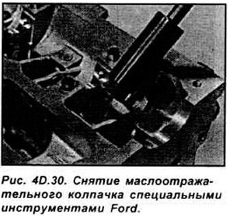
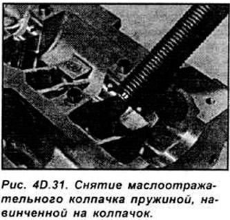
Using the special tool Ford 21-160, remove the oil deflector caps. If you do not have a special tool, the oil deflector cap can be removed by screwing a spring onto it, the inner diameter of which is slightly smaller than the outer diameter of the cap, and pulling the spring, remove the cap (see Fig. 4D.30, 4D.31).
Place the valve parts kits in plastic bags and label them for installation in their proper locations.
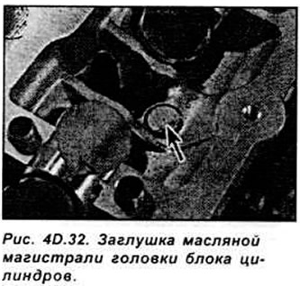
If it is necessary to remove the plug of the oil line in the cylinder head (for complete cleaning of the oil line), it is necessary to drill a hole in the plug and screw a self-tapping screw into it and pull the plug out by pulling the screw. When assembling the head, it is necessary to use a new plug (see Fig. 40.32).
Cleaning of parts
Clean off any traces of old gasket and sealant from the cylinder head.
Clean carbon deposits from the combustion chamber and cylinders, then wash the cylinder head with a suitable solvent.
Clean the passages in the cylinder head using a wire brush.
Checking the cylinder head
Carefully check the head for cracks and other damage. If there are cracks on the head, the head must be replaced.
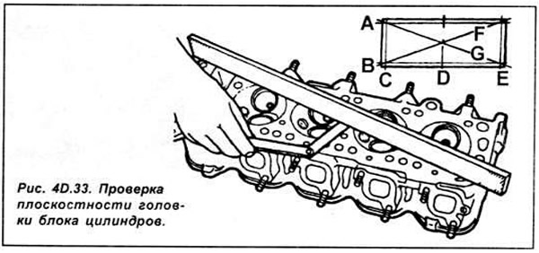
Using a metal ruler and feeler gauge, check the flatness of the mating surface of the head (see Fig. 4D.33).
Valve seats with signs of wear or burning must be processed with mandatory preservation of the angles and size of the chamfer. After any processing of valve seats, they must be ground in.
Check the internal diameters of the valve guides. If the values exceed the maximum permissible value, the valve guides should be replaced in a special repair shop.
Note: Replacing the guide also requires regrinding the seat of the corresponding valve.
Checking the valves
Inspect each valve head for pitting, burning, cracks and general wear.
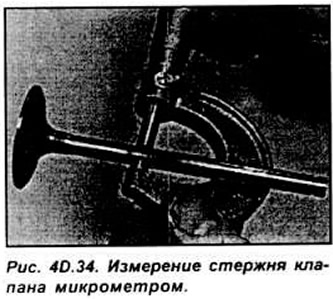
If the valve condition is satisfactory, measure the valve stem diameter at several points using a micrometer. Any significant difference in the obtained valve stem measurement data indicates stem wear. In this case, the valve must be replaced.
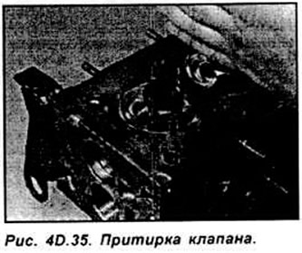
If the valves are in satisfactory condition, they need to be ground in. The valves need to be ground in using only fine-grained polishing paste. Lubricate the surface of the valve seat with a small amount of paste and install the valve in the corresponding seat. Press the rubber suction cup tightly to the valve plate and rotate the valve in one direction or the other.
After finishing the grinding process, thoroughly clean all parts from dirt and paste. Check the valve seat and plate. A solid matte ring should be visible on both parts, which indicates the width of the valve chamfer.
Checking valve parts
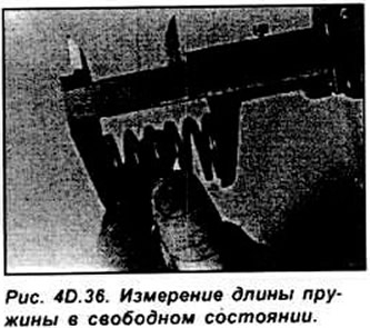
Check the valve springs for wear and delamination and measure their free length. If possible, compare each of the existing springs with the new spring (see Fig. 4D.36).
Place the springs on a flat horizontal surface and check their deviations from the horizontal position. If at least one of the springs is damaged, replace all the springs in the set.
Check the condition of the valve crackers, as well as the cracker installation locations on the valve. If there are any defects, the damaged parts must be replaced. The oil-deflecting caps must be replaced each time they are removed. Check the valve train components and hydraulic tappets.