2. Put the engine upside down.
3. Turn off bolts of radical bearings and take out covers. Set them aside in a certain order so that you can install them correctly later.
4. If it is difficult to pull them out, remove them together with the bearing shells. Wipe the surfaces of the bearing block and bearing caps with a soft, lint-free cloth. They shouldn't be dirty.
5. Clean the rear surfaces of the new bearing shells and place one half of the bearing in the block socket. Place the other half of each bearing in the corresponding cap. Make sure that the bearing shell lug fits into the corresponding recess in the block or cover. The oil holes in the block must also line up with the oil holes in the bushing. Do not drive the bearing into the seat with a hammer, do not knock or scratch its working surfaces. Do not use grease when installing the bearing.
6. A thrust bearing with a flange is installed in the third cover and the third seat.
7. Clean the bearing surface in the block and the main bearing journals on the crankshaft with a clean, fine-fibre cloth. Check and clean the crankshaft oil inlet holes, as dirt comes out through the new bearings.
8. If you are sure that the crankshaft is completely clean, carefully place it in the bearings.
9. Before the final installation of the crankshaft, check the oil clearance of the main bearings.
10. Roll several cylinders of a certain size from plasticizer (they should be slightly shorter than the width of the main bearings) and place one on each crankshaft main bearing journal, parallel to the axis of the journal (see picture).
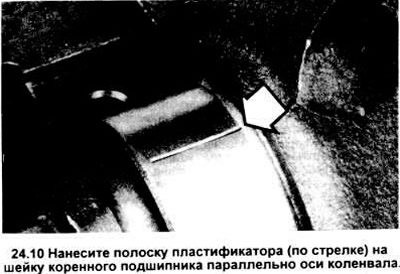
11. Clean the working surfaces of the bearing caps, reinstall the caps (don't mix them up), so that the arrows point towards the front of the engine. Do not move the plasticizer while doing this.
12. Tighten bolts of covers of radical bearings to the demanded value of the moment of an inhaling in three steps; when doing this, start with the central main bearing and move alternately to the edges. Do not move the crankshaft during this operation.
13. Turn off bolts and carefully remove covers of radical bearings Lay them out in order. Do not touch the plasticizer, do not turn the crankshaft. If any of the covers won't come off, gently tap the sides of the cover with a padded hammer.
14. Compare the wrinkled plasticizer strip width on each neck with the scale printed on the plasticizer box; you will get the oil clearance value of the main bearing (see picture). Compare with the data in the specification and make sure its value is correct.
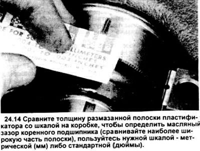
15. If the gap does not match the specification, this may indicate an incorrect selection of the liner size (which means you need other inserts). Before purchasing other liners, make sure that dirt and oil do not get into the liners, covers or block when checking the gaps. If the plasticizer turned out to be wider at one end, this indicates a possible tapered shaft neck (see section 20).
16. Carefully scrape off the remaining plasticizer from the journals under the bearings and from the working surfaces of the latter. Do not hit or scratch work surfaces.
17. Carefully remove the crankshaft from the engine. Clean the contact surfaces of the bearings in the block, then apply a thin, continuous film of type "moth" or special grease for engine components on the surface of the bearings. Be sure to lubricate the running surfaces and the shaft journal under the thrust bearing.
18. Make sure the journals of the crankshaft are clean, then put it back into the engine block. Clean the bearing surfaces in the caps, then apply grease to them.
Replace the covers so that the arrows on them point towards the front of the engine. Remember that on V6 engines, the rear cover is treated with a special sealant (Ford D6AZ - 19562 - A or similar), which is applied in a layer with a thickness of 3.175 mm (1/8 inch) on the line of contact of the rear main bearing cap with the block.
Install bolts (see picture).
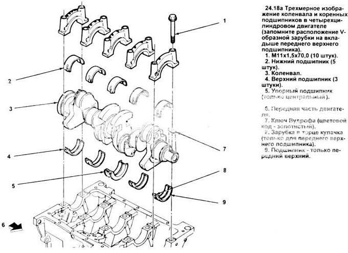
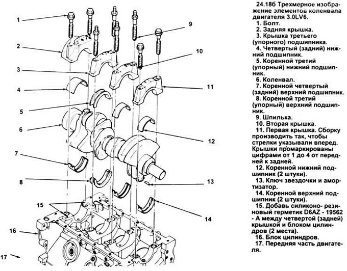
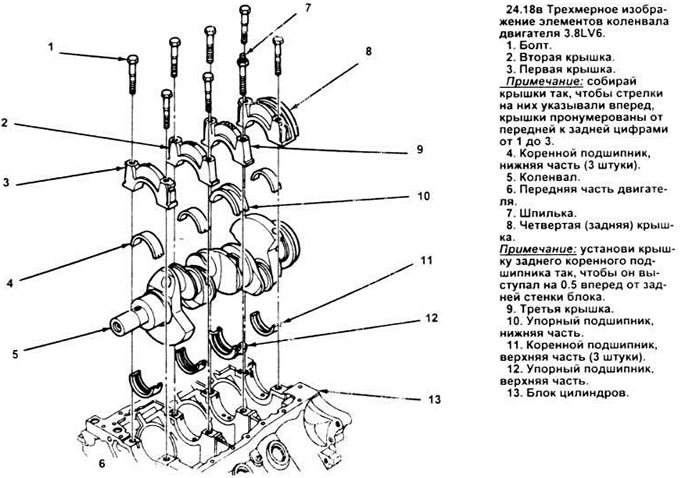
19. Tighten all bolts except for the third cover (from thrust bearing) to the required tightening torque (start with the central ones, achieve the desired tightening torque in three steps).
Tighten the bolts of the third cover to 13.56-16.27 Nm, (10-12 ft.lbs). To align the thrust surfaces of the main bearing and crankshaft, move the crankshaft back and forth while tapping it with a lead or bronze hammer. Retighten the main bearing bolts to the correct torque, starting with the third main bearing and working towards the edges.
20. On manual transmission models, install a new pilot bearing at the end of the crankshaft (see chapter 8).
21. Rotate the crankshaft several times by hand to check for possible binding.
22. At the last stage, it is necessary to check the axial play of the crankshaft with a feeler gauge or indicator, a description of the check is given in section 19. If the thrust surfaces of the crankshaft are not worn or damaged and new bearings are installed, then the axial clearance should be within the normal range.
23. For oil seal installation procedure, see section 13.
Visitor comments