2. Remove the cover from the first connecting rod. Remove the old bearing shells and wipe the running surfaces of the connecting rod and cap with a clean, lint-free cloth. They must not be dirty.
3. Clean the rear surface of the top half of the new bearing, then lay it in place in the connecting rod. Make sure that the bearing tab fits into the connecting rod groove. Do not hit the bearing shell with a hammer, and in any case do not hit or scratch its working surface. During assembly, the bearing is not lubricated.
4. Clean the back of the other bearing shell. install in the connecting rod cap. Again check the entry of the bearing tongue into the groove of the connecting rod, do not apply grease. When assembling a bearing with a connecting rod, it is extremely important that their contact surfaces are absolutely clean, including from grease.
5. Position the rings on the piston so that their cuts are at an angle of 120 degrees to each other (see picture), then put a piece of plastic or rubber hose on top of each connecting rod cap bolt.
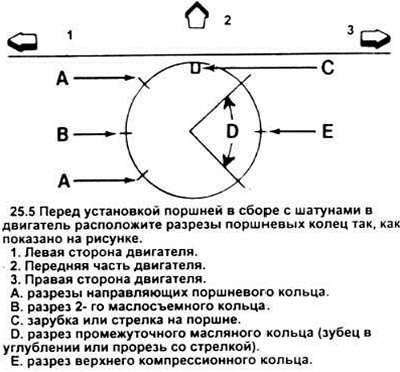
6. Lubricate the piston and rings with clean engine oil, install the piston in the piston-to-cylinder installer. Leave the piston skirt protruding from the tool by 6.35 mm (1/4 inch), to guide the piston into the cylinder.
Tighten the rings until they are flush with the piston.
7. Turn the crankshaft until. until the neck of the first connecting rod is at BDC (bottom dead center), then liberally lubricate the cylinder walls with oil.
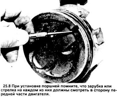
8. Turn the notch or arrow at the top of the piston toward the front of the engine (see picture), then carefully insert the piston with the connecting rod into the hole of the first cylinder and lower the lower edge of the tool onto the engine block. Tap the jig on top to make sure it contacts the block all the way around.
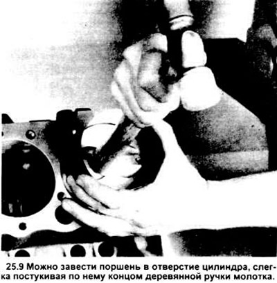
9. Gently tapping the piston from above with the end of the wooden handle of the hammer (see picture), put the connecting rod into the socket on the shaft journal. When entering the hole, the piston rings may pop out of the tool, so try to press the tool against the block. Proceed slowly, and if you feel resistance as the piston enters the cylinder, stop immediately.
Caution: under no circumstances try to push the piston into the cylinder by force, otherwise you risk breaking the rings or the piston itself.
10. After installing the piston assembly with the connecting rod, check the oil clearance of the connecting rod bearing, then finally screw the connecting rod cover into place.
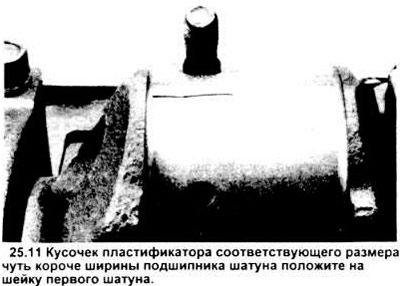
11. Cut a piece of plasticizer of the appropriate size slightly shorter than the width of the connecting rod bearing and place it on the neck of the first connecting rod parallel to its axis (see picture).
12. Clean the working surface of the connecting rod cap, then remove the protective pieces of hoses from the connecting rod bolts and install the cover. Make sure the mark on the cap is on the same side as the connecting rod mark. Tighten the nuts to the correct torque three times each.
Note: Use a thin-walled socket to avoid erroneous tightening torques that can result from the socket being pinched between the cap and the nut. Do not move the crankshaft during this operation.
13. Remove the connecting rod cap, being careful not to damage the plasticizer. Compare the thickness of the smeared plasticizer layer with the scale printed on the box, find the corresponding oil gap value (see picture). Compare the gap with the specifications. If the clearance does not match the required, this may indicate incorrectly selected bearing shells (in this case they will have to be replaced). Just in case, it does not hurt to make sure that no dirt or oil got between the liners, covers or connecting rods when measuring. Recheck neck diameter. If the smeared plasticizer turned out to be wider on one side, this may be a tapered neck of the shaft (see section 20).
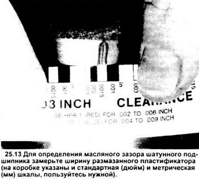
14. Carefully clean the remaining plasticizer from the neck of the connecting rod and its surface. In no case do not scratch the bearing - act with a fingernail or a wooden chip. Make sure the bearing surfaces are perfectly clean, then apply a regular thickness coat of type grease to both "moth" or engine oil. To install the bearing shell correctly in the connecting rod, you will have to push the piston into the cylinder; do not forget to put pieces of hoses on the connecting rod bolts first.
15. Lower the connecting rod into its socket on the neck, remove the pieces of hose from the connecting rod cap bolts, install the cap and tighten the nuts to the required torque in three steps.
16. Repeat the procedure for the remaining assemblies of pistons with connecting rods. When assembling, keep the backs of the bearing shells and the inner working surfaces of the connecting rods and caps immaculately clean. Check the correct selection of the piston to the cylinder and the installation of the pistons - so that the notch on them points to the front of the engine.
Be sure to lubricate the piston liberally with engine oil before installing it in the fixture. When final installation of connecting rod caps properly lubricate the bearings.
17. With the piston and connecting rod assemblies installed as expected, turn the crankshaft several times to detect possible seizing.
18. At the final stage, the axial runout of the connecting rod should be checked. This procedure is described in section 13. Compare the measured value of axial runout with that specified in the specification, make sure it is acceptable. It should remain within the allowable aisles, if it was before dismantling the old crankshaft and connecting rods. If new connecting rods or a new crankshaft were installed, the end play may be too small. Then you have to remove the connecting rods and bring them to the desired size.
Visitor comments