Features of the device
The piston is die-cast from aluminum alloy. The piston crown is flat, with recesses for valve plates (except GLA). Just like the cylinders, the pistons of the nominal size are divided into four groups with an interval of 0.01 mm. These groups are distinguished by the marking applied to the piston crown. When repairing the engine, it is necessary to measure the cylinders and pistons, and if the gap exceeds 0.15 mm. select pistons for cylinders, ensuring the required clearance in the mating. According to the diameter of the hole in the bosses for the piston pin, the pistons are divided into four groups through 0.003 mm. Steel piston pins, ground, are pressed into the upper head of the connecting rods and rotate freely in the piston bosses. The length of the piston pins for engines of the GMA, GPA and GLA models: 63.00-63.80 mm; for other engines; 66.20-67.00 mm The diameter and marking of the piston pins are the same as the holes in the piston bosses.
Each piston has three rings - two compression rings and one oil scraper ring. When installing the oil scraper ring, spread the locks of its elements by 120°. The gap in the lock of the lower oil scraper ring should be at an angle of 90°. And the upper compression ring - at an angle of 150° in relation to the lock of the oil scraper ring.
Connecting rods are steel, forged, I-section. A bushing is pressed into the upper head of the connecting rod, and thin-walled liners are installed into the lower head during assembly.
Disassembly and assembly of the connecting rod and piston group
The piston pin is removed using a press and a mandrel. Before assembly, it is necessary to check the bending and twisting of the connecting rod on a test plate.
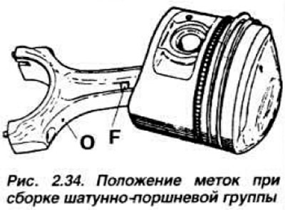
NOTE: When assembling, ensure that the arrow on the piston points in the same direction as the oil hole and the "F" mark on the connecting rod (Fig. 2.34).
Install the piston on the device (Fig. 2.35), with the arrow pointing away from the device.
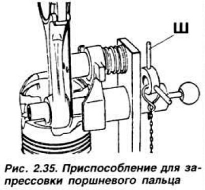
Lubricate both holes in the piston bosses for the piston pin with engine oil and insert the guide mandrel of the pin into the hole in the device. Insert the piston pin into the piston boss up to its inner end. Install the template with the "Essex" mark in the device. Heat the upper head of the connecting rod to a temperature of 260-400°C. Monitor the temperature with a thermochromic pencil. Quickly insert the connecting rod into the piston and press it against the shoulder of the guide mandrel. Press the piston pin in until it stops. Allow the assembled unit to cool before removing it from the device. It is impossible to change the position of the piston pin after the connecting rod has cooled due to significant interference.