Contents: Disassembly ↳ Assembly ↳
Attention! This section applies to all types of gearboxes.
Disassembly
1. Remove the release bearing and clutch release forks.
2. Secure the gearbox to the workbench.
3. Unscrew the ten mounting bolts and remove the gearbox cover.
4. Turn the gearbox over and drain the oil.
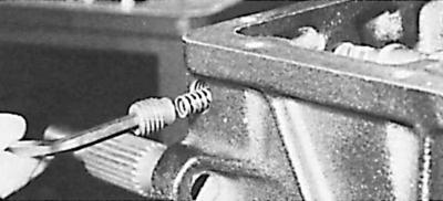
5. Using a screwdriver inserted into the hole for the gear selector shaft, remove the cover located on the end of the rear part of the gearbox housing.
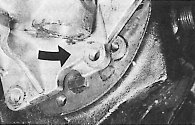
6. Unscrew the internal gearshift mechanism locking plug on the side of the crankcase, remove the spring underneath it and pull out the stopper using a magnetized rod.
7. Remove the pin from the locking unit, as well as the plug at the rear of the crankcase, and remove the cotter pin.
8. Remove the reverse gear selector cam pin and pull its shaft back.
9. Remove two pairs of forks and two stoppers.
10. Using tool 17.001, remove the sealing ring from the rear of the gearbox housing (the secondary shaft must be in place).
11. Unscrew the bolts securing the rear part of the gearbox housing, disconnect it from the front part of the housing and, by gently turning it in both directions, remove the intermediate shaft.
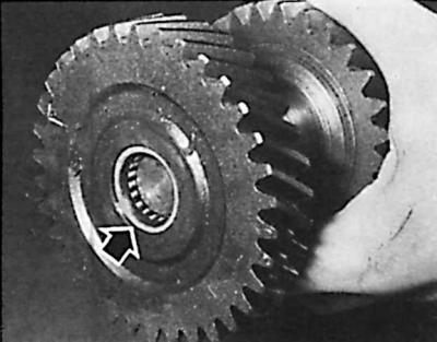
Attention! The intermediate shaft is a block of five gears that form a single unit and rotate on bearings located on the axis.
12. Move the intermediate shaft rearward to release it from the front stop.
13. Remove the intermediate shaft using tool 16.002, holding the shaft bearing with an auxiliary tool placed against the shaft being removed so that the bearing remains in place.
14. Remove the rear part of the gearbox housing.
15. Unscrew the four bolts securing the primary shaft bearing. Remove the primary shaft together with its needle bearing.
16. Remove the gear block from the intermediate shaft axle using the auxiliary tool and remove the two thrust washers from the gearbox housing.
17. Remove the ring from the reverse gear lever axle and remove the lever.
18. Remove the speedometer drive gear cover and remove the gear from the rear of the transmission case.
Assembly
1. Thoroughly clean all gearbox parts and lubricate them with gearbox oil. The threads of the bolts entering the gearbox housing should be coated with sealing paste.
2. Insert the reverse gear lever onto the axle and secure it with the ring.
3. Install the reverse intermediate gear on this lever; the forks are directed backwards; install the gear opposite the axle, lubricated with consistent grease, and use a copper hammer to push the gear into place.
4. Install the thrust washers of the intermediate shaft gear block in the recesses provided for them in the crankcase using consistent grease.
5. Carefully insert the intermediate shaft gear block into the gearbox housing. Install the thrust washers with the protrusions in the corresponding recesses.
6. Install the primary shaft and its bearing in the gearbox housing. Rest the spring mounting ring against the housing wall.
7. Install the precision primary shaft bearing with a new O-ring and tighten the four mounting bolts, coating the threads with sealing paste.
8. Insert the oiled needle bearing onto the primary shaft and install the 3rd–4th gear synchronizer sleeve.
9. Install the rear part of the gearbox housing and the secondary shaft. Turn the housing so that the intermediate shaft axle can be inserted (the gasket on the housing joint surface should be glued with grease to protect it from damage).
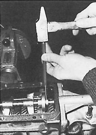
10. Tilt the gearbox so that the intermediate shaft gears mesh with the primary shaft gear and the secondary shaft gears. Check that the two thrust washers are in place. Insert the intermediate shaft axle into the rear of the housing with brass hammer blows, keeping it in contact with the mounting pin until its top is level with the clutch housing. The flat projection at the rear of the intermediate shaft axle should be horizontal.
11. Install the rear part of the gearbox housing on the extension of the front part, lubricate the threads of the mounting bolts with sealing paste and tighten them to the appropriate torque.
12. Using tool 16.016, insert the ring into the rear of the crankcase. Check whether the oil return channel from the rear of the crankcase and the cutout in the ring are in line.
13. Fill the rear crankcase sealing ring with grease and insert it using tool 16.016.
14. Insert the speedometer drive gear and screw on the cover, lubricated with sealing paste.
15. Install the locking mechanism plate and secure it with the pin. Insert a new plug (coated with sealing paste) into the rear of the front part of the gearbox housing.
16. Insert the two axles together with the forks, as well as the reverse gear lever. Insert the selector axle from behind the crankcase. Install the ring on the selector axle, as well as its hub.
17. Screw on the selector shaft locking stopper, insert the spring and plug into the side of the crankcase.
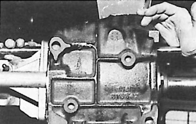
18. Install the rear gearbox housing cover and secure it in three places around the perimeter of the cover.
19. Install the cover onto the front of the transmission housing.
20. Bolt the clutch housing to the front of the gearbox housing (if it is separate in this version).
21. Remove the gearbox from the work bench and insert the release forks and clutch release bearing into the gearbox housing.