Gears and shafts of a mechanical five-speed gearbox
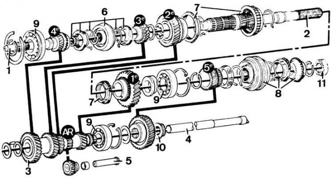
1 – primary shaft; 2 – secondary shaft; 3 – intermediate shaft constant mesh gear; 4 – intermediate shaft gear block axis; 5 – axle of intermediate gear of reverse gear; 6 – 3rd–4th gear synchronizer; 7 – 1st–2nd gear synchronizer; 8 – 5th gear synchronizer; 9 – ball bearing; 10 – 5th gear fastening nut on the intermediate shaft; 11 – speedometer drive gear.
The black circles show the gear numbers of individual gears (AR – reverse gear).
Gear shift mechanism of a five-speed gearbox
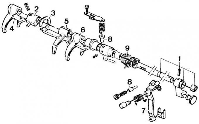
1 – control shaft; 2 – selector; 3 – spring lock ring; 4 – 3rd–4th gear forks; 5 – 1st–2nd gear forks 6 – 5th gear forks; 7 – reverse gear engagement lever; 8 – spring lock pin; 9 – spring
Disassembling the secondary shaft
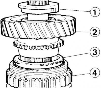
1 – sealing ring; 2 – 1st gear pinion; 3 – 1st gear synchronizer ring; 4 – 1st–2nd gear synchronizer
1. Remove the retaining ring from the 3rd–4th gear synchronizer hub and remove the synchronizer ring and 3rd gear gear.

2. Remove the retaining ring and two mounting half rings of the 2nd gear.
3. Remove the 2nd gear from the secondary shaft.
4. Remove the speedometer drive gear from the secondary shaft.
5. Remove the synchronizer and 5th gear from the secondary shaft.
6. Remove the bearing retaining ring from the secondary shaft and remove the secondary shaft from the center section of the gearbox housing.
7. Remove the sealing ring, 1st gear gear and 1st gear synchronizer ring from the secondary shaft (see Fig. Disassembling the secondary shaft).
8. Remove the secondary shaft bearing from the middle section of the gearbox housing.
Secondary shaft assembly
1. Before assembly, lubricate the surfaces of interacting parts with gearbox oil.
2. Install the secondary shaft bearing in the middle part of the gearbox housing and secure the retaining ring of this bearing.
3. Install the spring rings on the synchronizer hubs.
4. Install the 1st gear synchronizer ring and 1st gear on the secondary shaft.
5. Install the sealing ring on the secondary shaft with the working edges facing away from the bearing (see Fig. Disassembling the secondary shaft).
6. Install the bearing, secondary shaft and retaining ring in the middle part of the gearbox housing.
7. Install the bearing, secondary shaft and retaining ring in the middle part of the gearbox housing.
8. Install the 5th gear pinion, sealing ring and 5th gear synchronizer onto the secondary shaft.
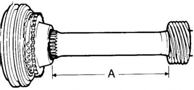
9. Install the speedometer drive gear on the secondary shaft. Observe the distance A = 123±0.5 mm.
10. Install the 1st-2nd gear synchronizer on the secondary shaft. The groove (for the forks) on the sliding sleeve of this synchronizer should be directed forward.
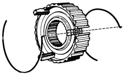
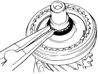
Install the synchronizer ring, 2nd gear pinion and two mounting half rings and a retaining ring (the figure shows the installation of the retaining ring of the 3rd–4th gear synchronizer).
Install the 3rd gear pinion, 3rd–4th gear synchronizer and retaining ring on the secondary shaft.
If the synchronizer has been disassembled, then when assembling it, you should make sure that the groove on the sliding sleeve is directed forward.
Disassembly and assembly of the intermediate shaft gear block
Disassembling the intermediate shaft gear block is not particularly difficult. Care should be taken not to lose the bearing needles and the spacers (front and rear) of the needle bearings. When assembling, carefully install the two spacers and coat the bearing needles with grease so that they do not fall out during the installation of the gear block shaft.
(For more information, please visit the website: «FORDBOOK.ru»)