Gears and shafts of gearboxes type A and B
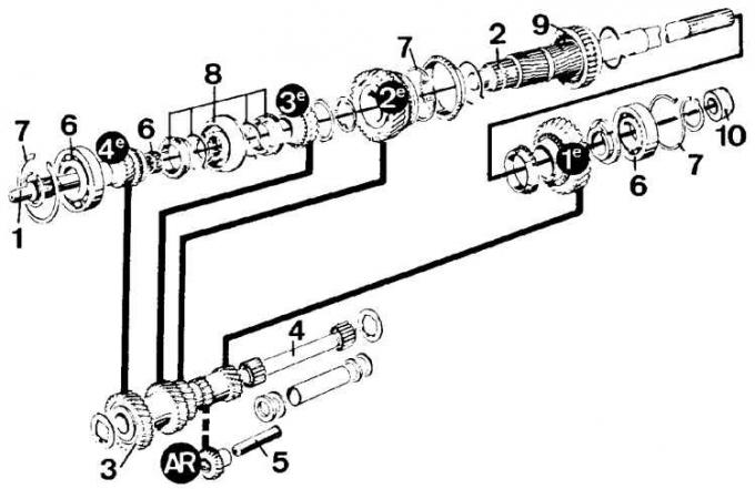
1 - input shaft; 2 - secondary shaft; 3 - gear wheel of constant engagement of the intermediate shaft; 4 - the axis of the block of gears of the intermediate shaft; 5 – an axis of an intermediate gear wheel of a reverse gear; 6 - precision bearing; 7 - retaining ring; 8 - synchronizer of 3rd-4th gears; 9 – synchronizer of 1st–2nd gears; 10 - speedometer drive gear.
The black circles show the gear numbers of the individual gears (AR - reverse gear).
Gearshift mechanism of type A and B gearboxes
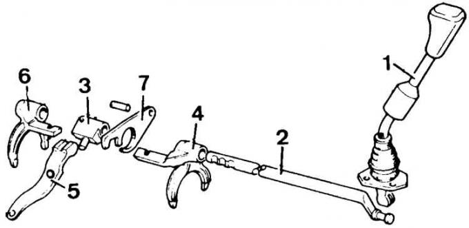
1 – gearshift lever; 2 - control rod; 3 - selector; 4 - forks 1st-2nd gears; 5 - reverse gear forks; 6 - forks 3rd-4th gears; 7 - plate of the locking mechanism
Dismantling the output shaft
1. Remove the pinion shaft precision bearing outer race from the rear of the transmission. Knock out the entire secondary shaft from the rear of the crankcase with a copper hammer.
2. Remove the snap ring from the 3rd-4th gear synchronizer hub and remove the synchronizer ring and 3rd gear.
3. Disconnect the 2nd gear and output shaft thrust washer circlip.
4. Remove the circlip of the 1st-2nd gear synchronizer hub and remove the synchronizer hub.
5. Remove 3rd-4th gear synchronizer. Disconnect the synchronizer hub and its springs.
Output shaft assembly
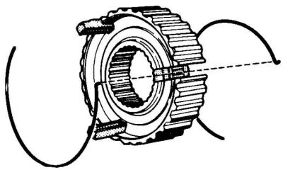
1. Insert the hub circlip and the 3rd-4th gear synchronizer. Install crackers on the hub and position the cutouts on both cones opposite each other. Insert retainer nut and spring. The bent ends of the two spring rings should be placed in one cracker.
2. Insert the synchronizer spring ring on the hub, the 1st-2nd gear synchronizer and lubricate the synchronizer.
3. Install the 1st gear on the output shaft, as well as the synchronizer sleeve and oil deflector.
4. Determine the thickness of the pinion shaft precision bearing snap ring.
5. Install the retaining ring in the groove at the rear of the gearbox housing and slide it all the way into the outer race of the precision bearing. Use a vernier caliper to measure the distance between the bearing stop surface and the top surface of the adjusting ring groove. Subtract the bearing width from the result to determine the thickness of the additional ring required. Select ring thickness from available spare parts (see subsection 6.1.1).
6. Fill the output shaft bearing seat with grease.
7. Press in the bearing and secure with a circlip.
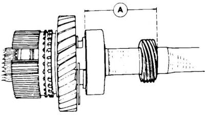
8. Install the speedometer drive gear. Distance between the front surface of the precision bearing and the speedometer drive gear (size A) should be 51.20 mm for gearbox type A and 49.25 mm for gearbox type B.
9. Install 1st-2nd gear synchronizer. The set marks on the hub and the synchronizer ring must be in line. Make sure that the sliding clutch with the reverse gear points to the rear.
10. Install the 2nd gear with circlip, synchronizer ring and thrust washer, and circlip onto the output shaft.
11. Install the 3rd gear synchronizer ring on the press on the output shaft.
12. Install the 3rd-4th gear synchronizer hub on the press on the output shaft, with the longer flange of the hub pointing forward and install the retaining ring.
13. Heat the rear of the gearbox housing by immersing it in hot water and install the output shaft and circlip.
Disassembly and assembly of the input shaft, as well as the gears of the intermediate shaft
1. Remove the circlip and bearing from the input shaft using a press or puller.
2. Coat the seating surface of the input shaft precision bearing with multipurpose grease, install the bearing on a press and insert the circlip.
3. Using a screwdriver, remove the O-ring fixed in the outer ring of the input shaft precision bearing. Fill the bearing with grease and insert the O-ring with a suitable bushing, with the sealing edge towards the gearbox housing.
4. Remove intermediate shaft axle, spacer and 19 bearing needles (gearbox type A), as well as thrust washers on both sides of the intermediate shaft gear block. Type B gearboxes (reinforced structure) has 21 bearing needles and does not have a spacer.
5. Insert the gear unit onto the intermediate shaft axle and fill the space between the axle and the inner surface of the gear unit hole with grease on both sides. Insert thrust washer, 19 or 21 bearing needle, spacer (gearbox type A) and the next thrust washer.
Visitor comments