Contents: Gears of a manual transmission of… ↳ Disassembling the secondary shaft ↳ Secondary shaft assembly ↳ Disassembly and assembly of the… ↳
Type C mechanical gearbox housing
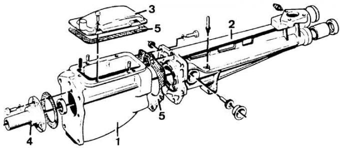
1 – front part of the crankcase; 2 – rear part of the crankcase; 3 – lid; 4 – Clutch release bearing guide sleeve; 5 – cover gasket
Gears of a manual transmission of type C
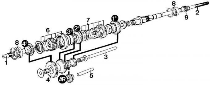
1 – primary shaft; 2 – secondary shaft; 3 – intermediate shaft gear block axis; 4 – intermediate shaft constant mesh gear; 5 – axle of intermediate gear of reverse gear; 6 – 3rd–4th gear synchronizer; 7 – 1st–2nd gear synchronizer; 8 – precision bearing; 9 – speedometer drive gear
The black circles show the gear numbers of individual gears (AR – reverse gear).
Gear shift mechanism of type C gearbox
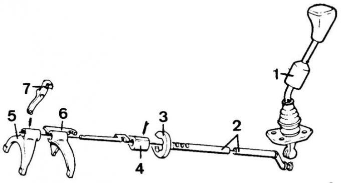
1 – gear shift lever; 2 – control rod; 3 – ring of the fixing device; 4 – selector; 5 – 3rd–4th gear forks; 6 – 1st–2nd gear forks; 7 – reverse gear forks
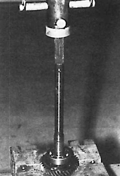
Disassembling the secondary shaft
1. Remove the retaining ring from its seat at the rear of the gearbox housing.
2. Remove the secondary shaft completely (by hitting it with a copper hammer).
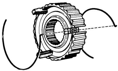
3. Remove the 3rd–4th gear synchronizer hub retaining ring, remove the synchronizer hub and 3rd gear gear (you can use a universal puller with two jaws).
4. Remove the retaining ring and remove the speedometer drive gear and latch ball from the secondary shaft.
5. Remove the retaining ring, precision bearing, and seal ring from the secondary shaft; during this operation, support the 1st gear pinion against a steel U-shaped support of appropriate dimensions.
6. Remove the 1st-2nd gear synchronizer hub retaining ring, and then remove the 1st-2nd gear synchronizer completely.
7. Remove the two synchronizer hubs, sliding clutches, and take out the crackers and springs.
8. Raise the car.
9. Clutch shield.
10. Lower bolts securing the clutch housing to the cylinder block.
Secondary shaft assembly
1. Thoroughly clean all parts and check their technical condition, and lubricate with gearbox oil before assembly.
2. When installing new factory parts, their working surfaces, as well as the interacting surfaces of the secondary shaft, should be coated with special S-MIC-4505 A grease.
3. "Glue" the locking crackers to the hubs of the 1st-2nd and 3rd-4th gear synchronizers using grease. Insert the sliding sleeves of the synchronizers onto the hubs and install them in accordance with their markings.
4. Insert the hub with the 1st-2nd gear synchronizer sleeve onto the secondary shaft, directing the sleeve groove intended for the forks back. Install the retaining ring.
5. Insert the synchronizer ring and 1st gear pinion. Insert the sealing ring so that its larger diameter is on the gear side.
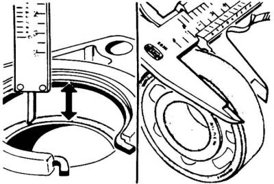
6. Determine the thickness of the required spring ring that secures the bearing on the secondary shaft. To do this, proceed in the same way as in the case for the type A gearbox (see subsection 6.1.4).
7. Install a ball bearing on the secondary shaft, as well as a retaining ring of the required thickness.
8. Coat the surface of the ball bearing with general-purpose precision bearing grease.
9. Press the ball bearing into place on the secondary shaft using a bushing of the appropriate size or other suitable universal tool.
10. Install the speedometer drive gear on the secondary shaft and install the secondary shaft so that the recess on the locking ball is on top. Install the locking ball in the socket, correctly install the speedometer drive gear on the shaft and secure with a retaining ring.
11. Install the 3rd-4th gear synchronizer on the secondary shaft with the annular thickening forward. Install the retaining ring.
12. Warm up the rear part of the gearbox housing by immersing it in hot water and install the secondary shaft in it.
13. Insert the retaining ring into the correct location. This ring should be in the socket at the rear of the gearbox housing.
Disassembly and assembly of the primary and intermediate shaft
1. Remove the retaining ring and bearing from the input shaft.
Attention! To facilitate subsequent installation of the bearing, install a large diameter retaining ring in its place.
2. Coat the input shaft precision bearings with general purpose grease, press in the bearing and remove the large diameter snap ring.
3. Remove the rod (inserted during the removal of the intermediate shaft axle) from the hole in the intermediate shaft gear block. Remove the 29 bearing needles and thrust washers from both sides of the intermediate shaft gear block.
4. Reinsert the removed rod into the hole in the gear block. Fill both sides of the rod with universal grease between the rod and the hole in the intermediate shaft gear block.
5. Install in order on both sides: spacer sleeve, bearing needle set and second spacer sleeve.
6. Using a screwdriver, remove the sealing ring from the outer ring of the primary shaft bearing.
7. Coat the edge of the sealing ring with general purpose grease.
8. Using a suitable tool, carefully press the new sealing ring into the input shaft bearing.