Special tool
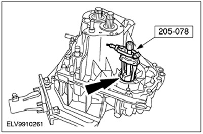
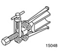 | Pinion Oil Seal Remover 205-078 (15-048) |
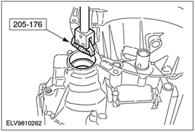
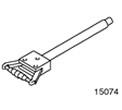 | Differential bearing ring remover 205-176 (15-074) |
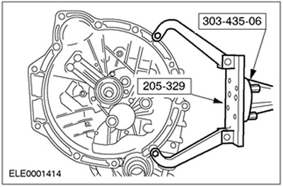
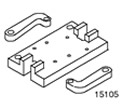 | Engine/Differential Assembly Stand 205-329 (15-105A) |
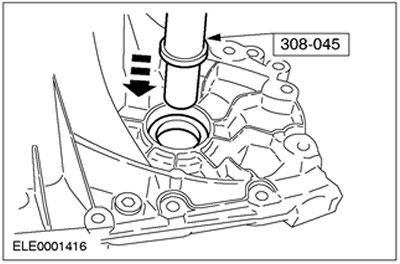
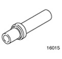 | Installer 308-045 (16-015) |
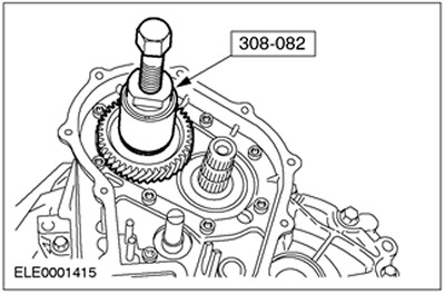
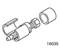 | 5th gear puller from input shaft 5th gear puller from input shaft 308-082 (16-035) |
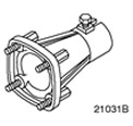 | Support bracket for 303-435 303-435-06 (21-031V) |
General equipment: Assembly stand.
1.
CAUTION: Handle the dual synchronizer elements with care.
General note
- Protective pads must be installed on the vise jaws during all operations.
- Use a copper or plastic mallet to avoid damage to the gearbox components.
2. Mount the gearbox on the assembly stand.
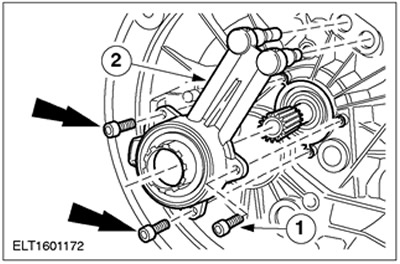
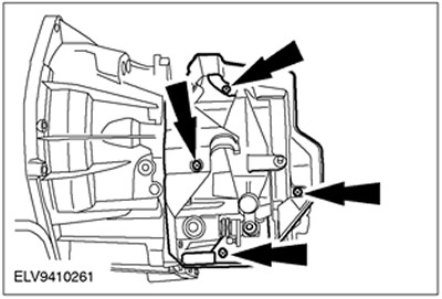
3. Remove the clutch slave cylinder.
- 1. Turn out bolts.
- 2. Remove the clutch slave cylinder.
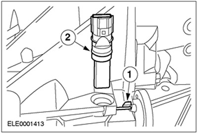
4. Remove the vehicle speed sensor (VSS).
- 1. Remove the pin.
- 2. Remove the VSS sensor.
5. Remove the shift cable cover.
6. Remove the gear selection lever.
- 1. Remove the protective cover.
- 2. Remove the retaining ring.
7. Remove brackets for shift cables and gear selection. Remove the cover.
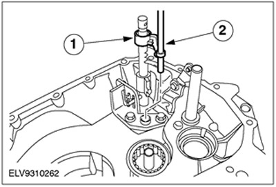
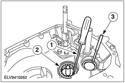
8. Remove the cover and gear selection locks.
- 1. Lid
- 2. 5th gear select lock mechanism
- 3. Mechanism of blocking of a shaft of a choice of transfers.
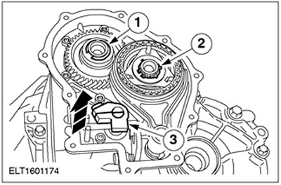
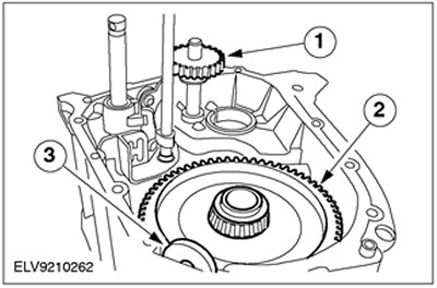
9. Remove a lock ring and a finger of a choice of transfers.
- 1. Remove the retaining ring from the 5th gear and discard it as no longer needed.
- 2. Remove the retaining ring from the 5th gear synchronizer assembly and discard it as no longer needed.
- 3. Remove the pin and discard it as no longer needed.
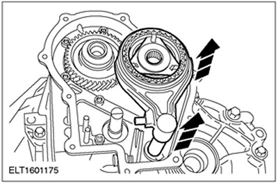
10. Remove the 5th gear synchronizer together with the gear selection fork.
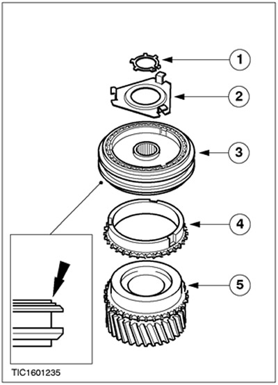
11.
NOTE: Before disassembly, note the installation position of the synchronizer.
Disassemble the 5th gear synchronizer.
- 1. Retaining ring
- 2. Lock bar
- 3. Synchronizer
- 4. Synchronizer ring
- 5. 5th gear
12. Remove the 5th gear.
13.
CAUTION: Do not hit the mating surface directly.
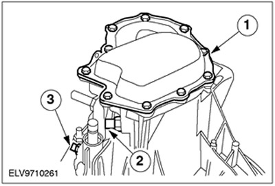
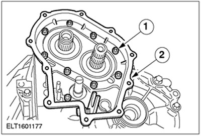
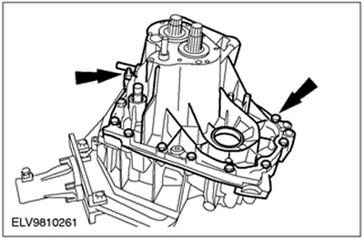
Remove the 5th gear housing.
- 1. Remove the bolts and carefully separate the sections of the 5th gear housing by lightly tapping on them.
- 2. Clean the mating surface.
14.
CAUTION: Do not hit the mating surface directly.
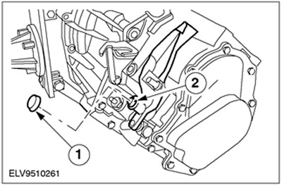
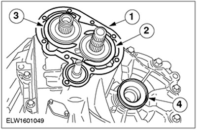
Remove retaining rings.
- 1. Remove seal and discard as no longer needed.
- 2. Remove the output shaft circlip and discard it as no longer needed.
- 3. Remove the input shaft snap ring and discard it as no longer needed.
- 4. Remove the process plug.
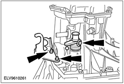
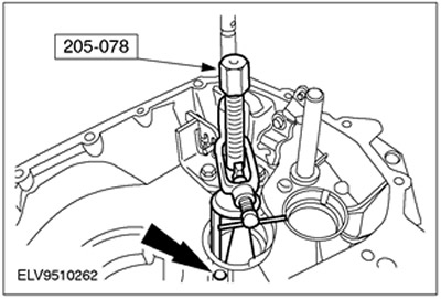
15. Remove both oil seals (left side shown).
- Using the special tool, remove the front axle oil seals.
- The reversing light switch should only be removed for sealing purposes.
16.
NOTE: Rotate the crankcase slightly to raise it (transmission vent pipe attached to input shaft).
Separate the sections of the gearbox housing.
- Remove the bolts and carefully separate the crankcase sections by lightly tapping on them.
- Clean the mating surface.
17. Remove the upper circlip from the gear selector rod guide.
- 1. Remove the top retaining ring and discard it as no longer needed.
- 2. Lower the selector rod guide bushing down.
18. Remove the selector rod guide bush.
- 1. Remove the lower retaining ring of the guide bushing and discard it as no longer needed.
- 2. Remove the selector rod guide bush.
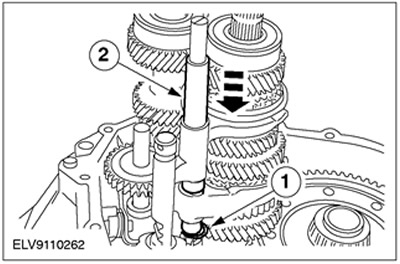
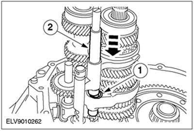
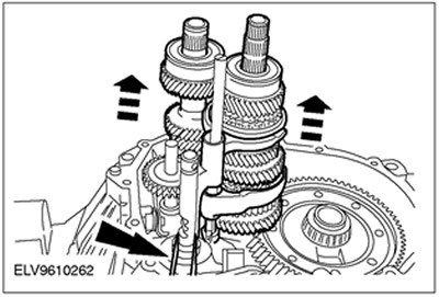
19.
NOTE: To facilitate disassembly, connect a rubber strap to the auxiliary select shaft.
Remove the primary and secondary shafts together with the gear selector forks.
20. Remove the reverse idle gear, differential and permanent magnet.
- 1. Idler reverse gear
- 2. Differential
- 3. Permanent magnet
21. Remove the gear selection rod along with the locking bar.
- 1. Shift stop sleeve
- 2. 5th/reverse selector rod
22. Remove the secondary shaft roller bearing.
- 1. Remove the rollers from the cage.
- 2. Remove separator.
- 3. Remove the axle shaft oil seal.
23.
CAUTION: Use the special tool in the indicated position. Otherwise, the plug will be removed from the crankcase.
Remove the secondary shaft bearing inner race. Remove the oil nozzle.
24.
NOTE: Refer to step 25 for disk installation sequence.
Remove the bearing inner race.
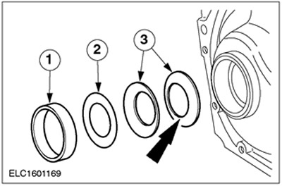
25. The sequence of installation of differential discs.
- 1. Bearing inner ring
- 2. Shim
- 3. Cup washers
26.
NOTE: Install the special tool in the crankcase recess.
Remove the differential bearing inner race.
Visitor comments