Special tool
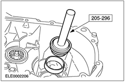
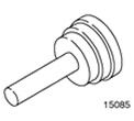 | Rear Wheel Hub Bearing Ring/Seal Installer 205-296 (15-085) |
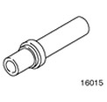 | Tool for installing oil seal of console part of gearbox housing 308-045 (16-015) |
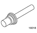 | Primary Shaft Oil Seal Installation Tool 308-039 (16-018) |
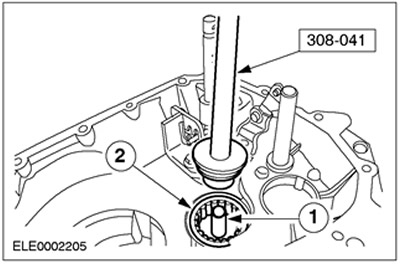
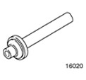 | Device for installing primary shaft bearing ring 308-041 (16-020) |
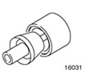 | Primary Shaft Snap Ring Installation Tool 308-076 (16-031) |
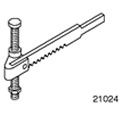 | Valve Spring Compressor 303-060 (21-024) |
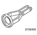 | Adapter for 303-060 303-060-02 (21-024-02) |
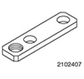 | Adapter for 303-060 303-060-07 (21-024-07) |
General equipment:
- Press
- Dial indicator
- Tripod with magnetic base for dial indicator
| Name | Specification |
| Universal sealant (Hylomar) | ESEE-M4G1008-A |
| End Cap Sealant | WSE-M4G323-A4 |
| Gearbox housing sealant | WSK-M2G348-A5 |
| Transmission fluid | WSD-M2C200-C |
1. Before assembly, carefully clean and check all parts.
- Lubricate all working surfaces. Transmission fluid is used for this.
2. Install the secondary shaft roller bearing together with the bearing inner race.
- 1. Install the oil nozzle.
- 2. Install the roller bearing.
3. Install the differential bearing inner race.
4. Install the 5th/reverse gear selector shaft together with the shift lock sleeve.
- 1. Shift lock bushing
- 2. 5th gear/reverse gear selection shaft
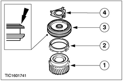
5.
NOTE: Reverse idler gear installation position
Install the reverse idler gear, differential assembly and permanent magnet.
- 1. Reverse intermediate gear
- 2. Differential
- 3. Permanent magnet
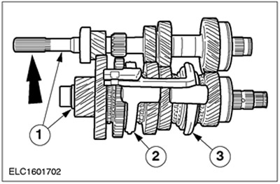
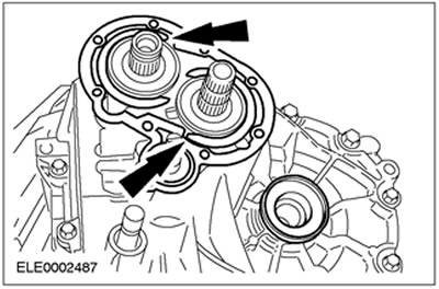
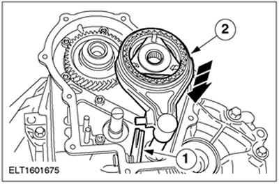
6. Prepare the primary and secondary shafts for installation.
- 1. Engage the primary and secondary shafts.
- 2. Move the 1st/2nd gear shift fork to the setting position.
- 3. Move the 3rd/4th gear shift fork to the setting position.
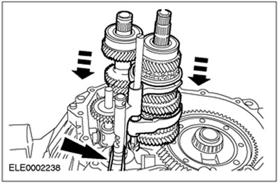
7. Install the primary and secondary shafts.
- To facilitate installation, attach a rubber belt to the gear selector shaft.
- Insert the input shaft to a depth of approximately 50 mm and turn it slightly to the side.
- Insert the secondary shaft to the level of the primary shaft and re-engage the gears.
- Check the position of the primary and secondary shafts.
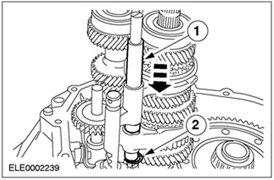
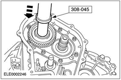
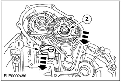
8.
NOTE: Install a new lower snap ring.
Install the gear selector shaft guide sleeve.
- 1. Install the guide bushing.
- 2. Install the lower retaining ring.
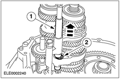
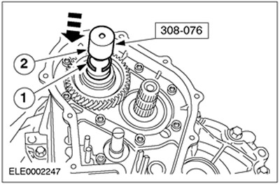
9.
NOTE: Install a new upper snap ring.
Connect the upper snap ring to the selector shaft guide sleeve.
- 1. Pull up the guide sleeve.
- 2. Install the upper retaining ring.
10. Shift the internal gear shift lever to 5th gear.
- Turn the gear selector shaft clockwise until it reaches the reverse/5th gear shift channel, then push it down.
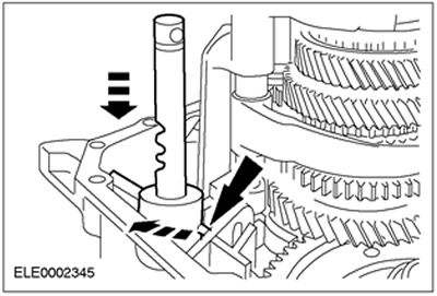
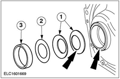
11. Install the measuring shim and secure it with a punch.
- 1. Gearbox housing
- 2. Measuring gasket (thickness 3.8 mm)
- 3. Inner bearing ring
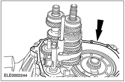
12.
NOTE: Clean the mating surface thoroughly.
Assemble the gearbox housing.
- Connect the special tool with a long bolt.
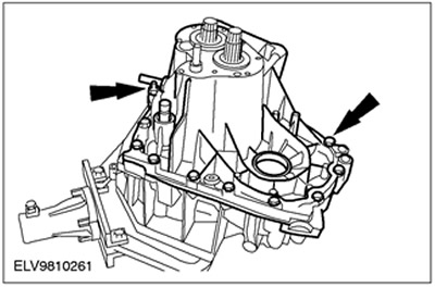
- Insert the technological plugs.
- Tighten the bolts.
- Rotate the gearbox 180 degrees.
13. Connect the special tool. Remove the technological plugs.
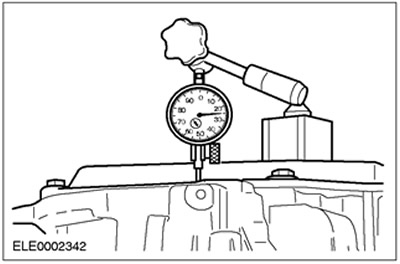
14. Prepare the differential for measurements.
- Rotate the differential assembly at least ten times to allow the bearings to settle into a stable position.
- Mount the dial indicator on the tripod with a magnetic base and set it to zero.
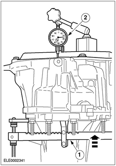
15.
NOTE: Perform the steps above and this step three times and calculate the average.
Measure the differential end play.
- 1. Using a special tool, lift the differential.
- 2. Take readings.
- Example:
- 1st measurement result: 0.73 mm
- 2nd measurement result: 0.74 mm
- 3rd measurement result: 0.72 mm
- Average = 0.73 mm + 0.74 mm + 0.72 mm/3 = 0.73 mm
- The thickness of the washer used should be rounded down for results up to 0.05 or less after the decimal point, and rounded up for results starting from 0.06 or more after the decimal point.
- Adjusting shims with a thickness from 0.1 mm to 1.1 mm with a resolution of 0.1 mm are provided.
- Proceed to the next item.
16. Determine the thickness of the gasket for installation (example).
- Adjusting shim thickness =
- Thickness of measuring gasket (3.80 mm) +
- Average value (0.73 mm) +
- Bearing preload (0.14) -
- Thickness of disc washer (4.42 mm) =
- 3.80 mm + 0.73 mm + 0.14 mm - 4.42 mm = 0.25 mm
- The thickness of the adjusting shim should be 0.25 mm, after rounding - 0.20 mm.
17. Separate the gearbox housing sections.
- Insert the upper technological plugs.
- Rotate the gearbox 180 degrees.
- Remove the dial indicator together with the stand and the special tool.
18. Remove the inner bearing ring together with the measuring shim.
19.
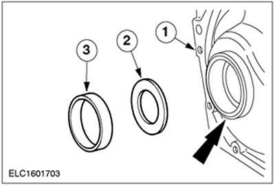
NOTE: Belleville washers contact on the inside diameter.
Install the adjusting shim of the calculated (rounded) thickness and secure it with a punch.
- 1. Disc washers
- 2. Adjusting shim of the calculated thickness.
- 3. Install the inner bearing ring and secure it by punching the edge of the crankcase.
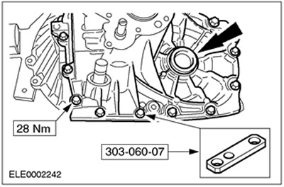
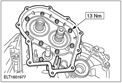
20. Apply sealant evenly to the gearbox housing.
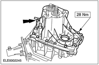
21.
NOTE: Tighten the studs to 33 Nm.
Assemble the gearbox housing and tighten the bolts evenly.
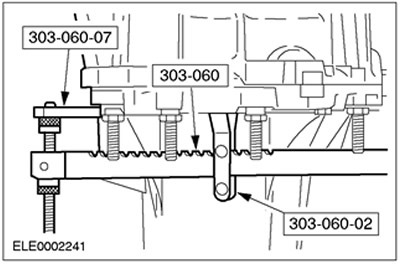
22.
NOTE: Install new snap rings on the input and output shafts.
NOTE: Use a wooden block.
Install the retaining rings on the primary and secondary shafts.
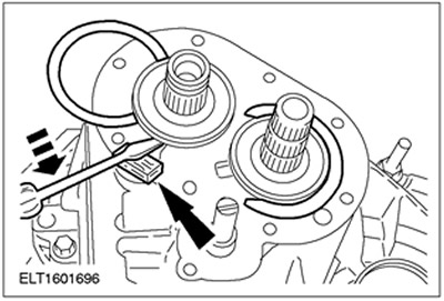
23.
NOTE: Rotate the retaining rings so that they are located in the slots in the gasket.
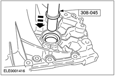
NOTE: Install a new seal to the 5th gear housing.
Install the 5th gear housing seal. Insert the access plugs.
24. Install the 5th gear housing.
25.
CAUTION: Remove the transmission from the assembly stand and perform the following steps on a press.
NOTE: The transmission case must not rest on the press table. Support the input shaft splines on the press.
Press the 5th gear onto the input shaft using a press.
- Remove the gearbox from the assembly stand.
- Press on the 5th gear using a press.
- Support the gearbox on an assembly stand.
26.
NOTE: Install a new 5th gear snap ring.
Install the 5th gear retaining ring.
- 1. Install the retaining ring on the special tool.
- 2. Install the special tool and fit the retaining ring.
27.
NOTE: Identification of synchronizer installation position.
Assemble the 5th gear synchronizer.
- 1. 5th gear pinion
- 2. Synchronizer ring
- 3. Synchronizer
- 4. Stop bar
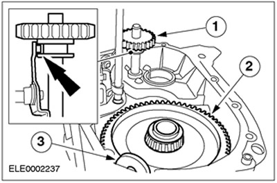
28. Install the 5th gear synchronizer together with the gear selection fork.
- 1. Turn the drive disc upward.
- 2. Install the 5th gear synchronizer so that it reaches the drive disc.
29.
NOTE: Do not tighten the shift hub bolt at this stage.
NOTE: Install a new 5th gear snap ring.
Install the 5th gear synchronizer and gear selector fork.
- 1. Install the gear selector finger.
- 2. Install the 5th gear synchronizer retaining ring.
30.
NOTE: Perform installation only with the transmission in neutral.
Position of installation of the gear selector shaft locking mechanism.
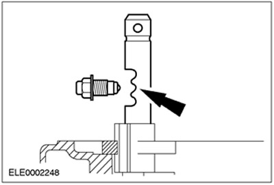
31.
NOTE: Perform installation only with the transmission in neutral.
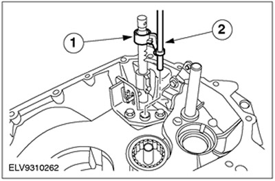
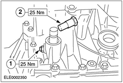
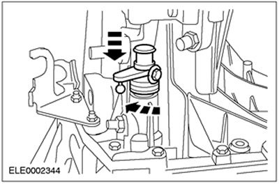
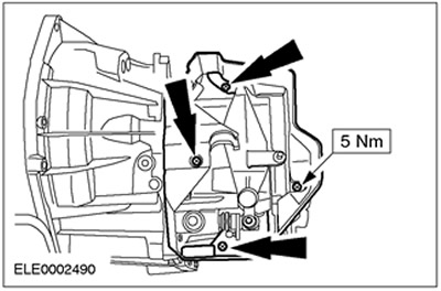
Install gear selector lock mechanisms.
- Apply universal sealant (Hylomar) to the threads.
- 1. Main locking mechanism
- 2. 5th gear locking mechanism
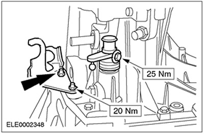
32. Install the shift and selector cable bracket. Install the boots.
33.
NOTE: Install the 5th gear lock mechanism.
Engage 5th gear. Press down the gear selection fork together with the gear selection finger.
34. Engage 5th gear. Turn the gear selector shaft clockwise through its entire travel.
35. Engage 5th gear. Turn the gear selector shaft clockwise through its full stroke and insert the shaft.
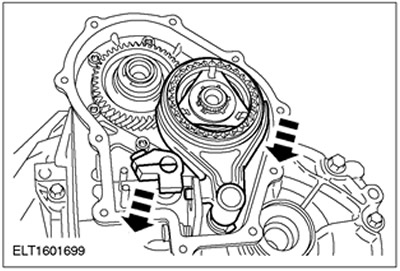
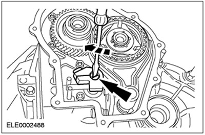
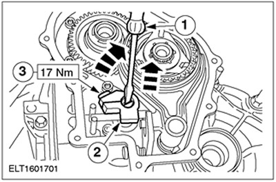
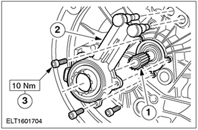
36. Adjust the gear selector finger.
- 1. Turn the gear selector shaft clockwise and press it down.
- 2. Lift the gear selector finger to eliminate axial play.
- 3. Tighten the bolts in this position.
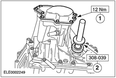
37. Install the end cover and input shaft oil seal.
- 1. Install the end cap using end cap sealant.
- 2. Insert the input shaft oil seal until it locks into place with a distinct click.
- Insert the technological plugs.
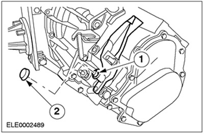
38. Install the shift lever.
- 1. Install the retaining ring.
- 2. Install the cover.
39. Install the gear shift cable cover.
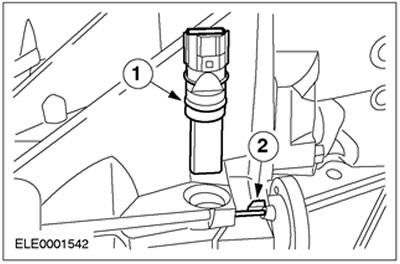
40. Install the vehicle speed sensor (VSS).
- 1. Connect the VSS sensor.
- 2. Insert the pin.
41. Install the input shaft oil seal and clutch slave cylinder.
- 1. Check the position of the input shaft oil seal.
- 2. Check the position of the clutch slave cylinder.
- 3. Tighten the bolts evenly. While doing this, press the input shaft oil seal into the gearbox housing.
42. Remove the gearbox assembly from the assembly stand.
(The original article is available on the website: «www.fordbook.ru»)