Insert tapered bearing (inner ring with baskets and rollers).
Insert the outer races of the tapered bearings into the gearbox housing.
Mounting the outer ring on the right (lesser) parts of the body should be performed according to fig. 3.25.
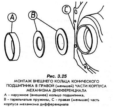
Lock the outer ring from rotation by securing it to the housing.
Install a new O-ring (stuffing box) semiaxes. The sealing lips must be on the inside of the gearbox and must be lubricated with oil before assembly.
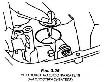
If the output shaft roller bearing has been removed, a new oil slinger must be installed (pic. 3.26).
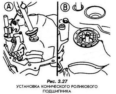
Install roller bearing using tool 16-020 (pic. 3.27).
Bearings with double-sided baskets must be installed so that the rear side of the basket is at the bottom. If necessary, you can use a chisel to cut the surface of the hole in the gearbox housing. The outer ring of the roller bearing is inserted into the hole prepared in this way.
This method is forced in conditions where it is not possible to replace the gearbox housing. The rigidity of the support in this case will be less than that obtained under normal mounting conditions.
Install to the left (big) part of the gearbox housing complete housing of the differential mechanism. The bearings must be generously lubricated with oil.
Install the reverse intermediate gear on the axle (pic. 3.28). At the same time, place the forks in the groove intended for them.

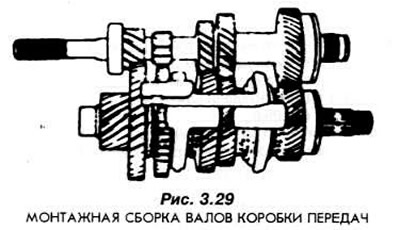
Put together as shown in fig. 3.29, both shafts of the gearbox. Set the forks in the grooves. Place the assembly in the gearbox housing and slide it against the shift lock plate. This plate must be rotated clockwise.
Insert the selector guide sleeve and install the first and second gear synchro forks on it. Secure the forks to the guide bushing with circlips.
Place a magnetic tab into the gearbox housing (pic. 3.30).
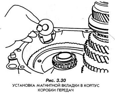
Install the left housing with a new gasket. Pay attention to the correct installation of the magnetic tab.
Tighten the mounting bolts of the installed body part to the correct torque.
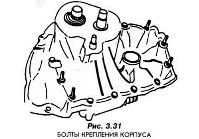
Lock the differential crown bevel gears from rotating. On fig. 3.31 shows the correct position of the mounting bolts of the installed housing.
Install expansion rings on the outer races of the ball bearings of the gearbox shafts (pic. 3.32).
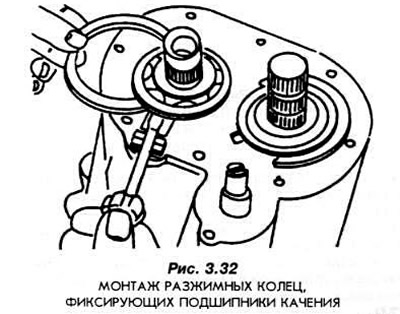
The circlips from the spare parts kits are available in three different thicknesses. You need to choose a ring that fits snugly into the groove of the bearings.
Mount the gearbox housing.
Lubricate the working surface of the hub of the fifth gear with paste "FORD SAM -1C9 107A".
Note: Gear and shaft splines must be marked with the same color.
Insert the fifth gear onto the shaft. During this operation, the shaft must be supported and secured from below.
Install with special tool 16-031 (pic. 3.33) retaining ring.
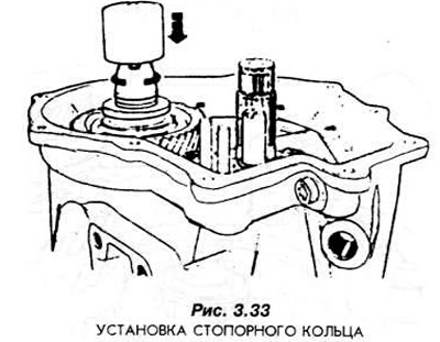
These rings in spare parts kits are available in three different thicknesses. It is necessary to choose a ring of such thickness that will ensure a tight fit of the ring in the groove.
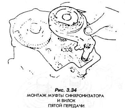
Mount and install the fifth gear driven gear with the synchronizer with the synchronizer clutch. The synchronizer must be complete with plugs (pic. 3.34). The coupling is selected in the previously described manner.
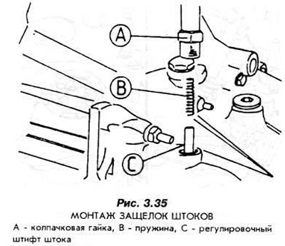
Insert the bolt pin and spring into the fifth gear housing. Tighten the cap nut firmly (pic. 3.35).
Insert the bolt pins and springs into the gearbox housing.
Both deadbolt systems must be installed before being installed in the correct positions of the fork stems.
Install the 5th gear forks and adjust the setting as follows:
- set the selector to the middle position.
- 5th gear stem push down and turn clockwise.
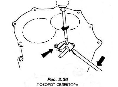
- turn on the fifth gear with the gearbox selector, to do this, turn the selector clockwise and at the same time pull it out completely (pic. 3.36).
- move the synchronizer clutch with the forks to the fifth gear driven gear.
- press the selector down and turn clockwise until it stops,
- raise the selector finger like this. so that there is no gap between the fifth gear bolt plate and the top of the pin.
- in this position, tighten the pin clamp bolt.
Install the transmission cover with a new gasket.
Check the operation of the gear change mechanism. including all transmissions in turn.
Install the release bearing and the shaft with the clutch release forks.
Screw the bracket to the gearbox.
Visitor comments