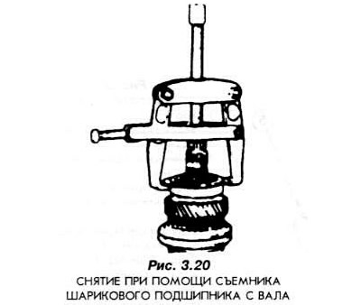
Using a puller, the jaws of which must enter the groove of the outer ring (Fig. 3.20), remove the ball bearing from the shaft. A bearing removed from the shaft in this way is not suitable for further use and must therefore be replaced with a new one.
Remove the fourth gear driven gear by hand.
Remove the third and fourth gear synchronizer hub retaining ring.
Remove the synchronizer hub together with the third gear gear.
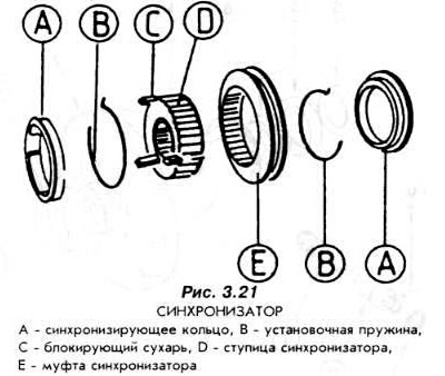
Remove the three-piece locking ring from the first and second gear synchronizer hub. Remove the moving parts of the synchronizer (Fig. 3.21).
- remove the synchronizer hub from the shaft,
- remove the synchronizing rings,
- remove the mounting springs,
- remove the crackers.
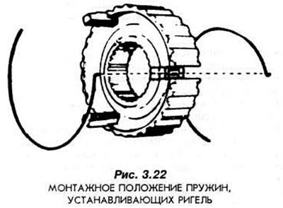
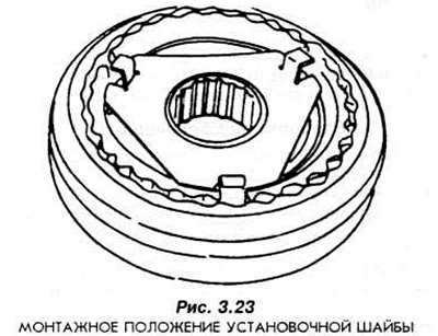
When assembling the synchronizer, the mounting springs must be mounted according to Fig. 3.22. The crackers are fixed with the washer shown in Fig. 3.23. The mounting spring must press on the crackers and must be located between the mounting washer and the synchronizer hub (Fig. 3.22 and 3.23).
The reverse gear intermediate shaft should not be removed, nor should any parts mounted on it be removed, as the ends of the shaft are tightly inserted into the housing.
For more information, please visit the specified website FORDBOOK