2. Assemble the intermediate and secondary shafts and hold this unit with a rubber bandage.
3. Install the reverse intermediate gear so that its annular thickening is directed towards the input shaft.
4. Use the next rubber band to hold this knot.
5. Place the entire assembly in the gearbox housing.
6. Place the speedometer drive gear together with the spacer sleeve onto the secondary shaft.
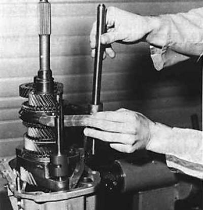
7. Check whether the intermediate shaft is correctly installed in the crankcase. Set its final position using tool 16.042.
8. Insert the rear reverse gear idler pinion shaft mounting bolt and tighten it by hand.
9. Remove the speedometer drive gear and spacer sleeve.
10. Insert the magnet into the gearbox housing.
11. Remove the rubber bandage.
12. Insert the 3rd and 4th gear forks with the undercut facing down, then the 5th and reverse gear forks.
13. Insert the axle of the forks of 3-4 gears, 5th gear and reverse gear.
14. Install the clutch housing on the gearbox housing, inserting three 25 mm thick spacers between the connecting planes of both housings.
15. Lubricate the connection surfaces with sealing paste.
16. Remove the three spacers and connect the crankcases using tool 16.041.
17. Insert two bolts into the holes connecting both crankcases and carefully connect them finally.
18. Insert the remaining eight connecting bolts and tighten all bolts to the appropriate torque.
19. Install the spacer sleeve and speedometer gear on the secondary shaft.
20. Using a bushing of the appropriate diameter, install a new sealing ring on the flange of the front joint of the propeller shaft.
21. Install the front cardan shaft joint flange onto the secondary shaft.
22. Screw in a new flange fastening nut on the rear end of the secondary shaft, having first lubricated the thread surface of the nut with sealing paste. After fixing the flange of the front joint of the cardan shaft, tighten the nut to the appropriate torque.
23. Lubricate the thread of the selector stop bolt with sealing paste, screw in the bolt and tighten it to the appropriate torque.
Caution! The sealing paste must not get inside the gearbox.
24. Press the selector stop sleeve into the crankcase until it stops.
25. Install the ball, pushrod and selector stop spring.
26. Lubricate the thread of the selector stop plug with sealing paste, screw the plug into the clutch housing and tighten it to the appropriate torque.
27. Screw in the front bolt securing the reverse gear intermediate gear shaft into the clutch housing and tighten both bolts (front and rear) to the appropriate torque.
28. Install a new snap ring onto the input shaft.
29. Install a new O-ring onto the clutch release bearing guide sleeve, install the sleeve inside the clutch housing and tighten its bolts to the specified torque.
30. Install a new O-ring onto the intermediate shaft bearing nut.
31. Screw in the intermediate shaft bearing nut at the front of the clutch housing and tighten it to a torque of 15–20 Nm.
32. Mark the position of the nut relative to the clutch housing and unscrew it by 60°.
33. Caulk the two protrusions located near this nut.
34. Check whether the intermediate shaft bearing rests on the mounting nut. This nut should not be able to be turned by hand. If not, repeat the last three steps after unscrewing the nut.
35. Install the intermediate shaft bearing nut retaining plate and tighten the retaining plate mounting bolt.
36. After applying a small amount of grease to the splines of the input shaft and the guide sleeve of the clutch release bearing, install the clutch release bearing together with the clutch release forks onto the input shaft.
37. Screw in the oil drain plugs and tighten them to the appropriate torque.
38. Fill the gearbox with the required amount of the appropriate gearbox oil.