Special tool
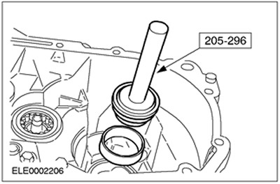
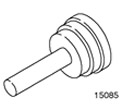 | Wheel Bearing Inner Ring/Seal Installer 205-296 (15-085) |
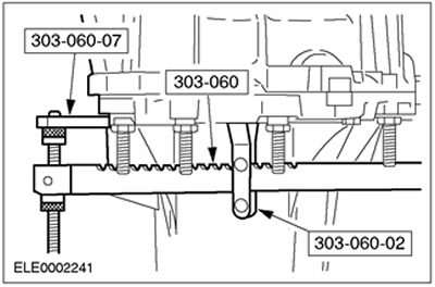
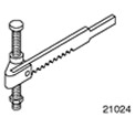 | Valve Spring Compressor 303-060 (21-024) |
 | Adapter for 303-060 303-060-02 (21-024-02) |
 | Adapter for 303-060 303-060-07 (21-024-07) |
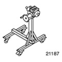 | Booth 303-435 (21-187) |
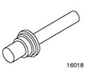 | Axle Seal Installation Tool 308-039 (16018) |
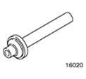 | Tool for installing the inner ring of the primary shaft bearing 308-041 (16-020) |
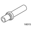 | Crankcase Protruding Section Bushing/Seal Installer 308-045 (16-015) |
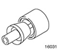 | Primary Shaft Snap Ring Installation Tool 308-076 (16-031) |
General equipment:
- Press
- Dial indicator
- Magnetic stand for dial indicator
- Technological plugs
| Name | Specification |
| Sealant | ESEE-M4G1008-A |
| Sealant | WSE-M4G323-A4 |
| Sealant | WSK-M2G348-A5 |
| Transmission fluid for manual transmission | WSD-M2C200-C |
| High temperature grease | ESDM-1C220-A |
1. Before assembly, carefully clean and check all parts.
- Apply clean manual transmission fluid to all working surfaces.
2. Using the special tool, install the secondary shaft tapered roller bearing and secondary shaft bearing outer race.
- 1. Install the oil funnel.
- 2. Install the tapered roller bearing.
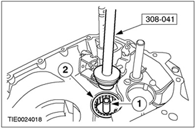
3. Using the special tool, install the outer ring of the differential bearing.
4. Install the 5th and reverse gear selector shaft and the shift lock sleeve.
- 1. Install the bushing.
- 2. Install the gear selector shaft.
5. Install the reverse gear intermediate gear.
6. Install the differential assembly and permanent magnet.
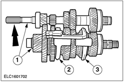
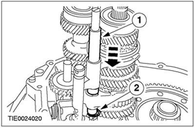
7. Prepare the primary and secondary shafts for installation.
- 1. Engage the primary and secondary shafts.
- 2. Move the 1st and 2nd gear shift forks to the installation position.
- 3. Move the 3rd and 4th gear shift forks to the installation position.
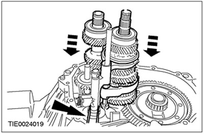
8.
NOTE: To facilitate assembly, install a rubber boot on the second gear selector shaft.
Install the primary shaft and secondary shaft.
- Insert the input shaft to a depth of approximately 50 mm and move it slightly to the side.
- Insert the secondary shaft to the level of the primary shaft and engage the gears.
- Install the primary shaft and secondary shaft.
9.
NOTE: Install a new snap ring.
Install the lower snap ring of the gear selector shaft guide sleeve.
- 1. Install the guide bushing.
- 2. Install the retaining ring.
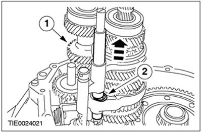
10.
NOTE: Install a new snap ring.
Install the upper snap ring of the gear selector shaft guide sleeve.
- 1. Lift the guide sleeve.
- 2. Install the retaining ring.
11.
NOTE: The surface of the shift lever pin must face the surface of the reverse idler gear lever.
Move the inner shift linkage towards the 5th gear pinion.
- Before pressing down, turn the selector shaft clockwise until it reaches the reverse and 5th gear channel.
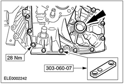
12. Install a 3.8 mm thick measuring shim and secure it with a punch.
- 1. Gearbox housing in block with drive axle
- 2. Measuring gasket
- 3. Outer bearing ring
13.
NOTE: Make sure all transaxle housing mating surfaces are clean.
Assemble the gearbox housing in block with the drive axle.
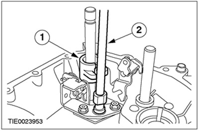
- Install the special tool.
- Install technological plugs.
- Install the bolts.
- Rotate the gearbox in the block with the drive axle by 180 degrees.
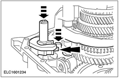
14. Install special tools. Remove technological plugs.
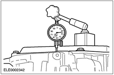
15. Using a suitable dial indicator, make a check measurement on the front surface of the gearbox housing in the block with the drive axle.
- Rotate the differential assembly approximately ten times to ensure bearing seating.
- Install the dial indicator and magnetic stand and adjust the dial indicator to zero.
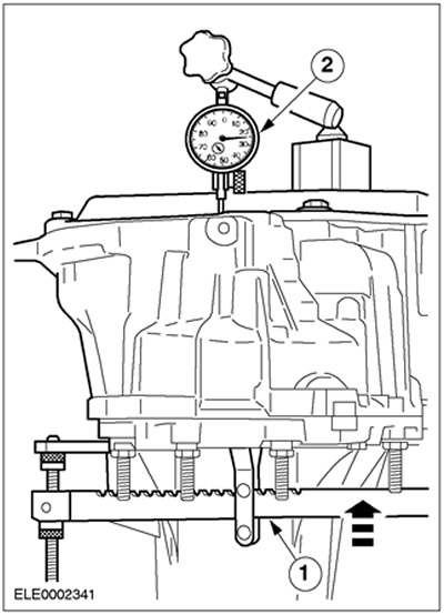
16.
NOTE: Perform the measurement procedure three times and calculate the average value.
NOTE: Adjusting shims are available in thicknesses from 0.1 mm to 1.1 mm in 0.1 mm increments.
Measure the differential end play.
- 1. Using the special tool, lift the differential assembly.
- 2. Record the measurement result (e.g. 0.73 mm).
- Example: 0.73 mm + 0.74 mm + 0.72 mm, divided by three = 0.73 mm.
- The gasket thickness value should be rounded down to the nearest tenth of a millimetre if the resulting value is 0.05 mm or less, and rounded up to the nearest tenth of a millimetre if the resulting value is 0.06 mm or more.
17. Calculate the required thickness of the adjusting shim.
- Adjusting shim thickness = shim size (3.80 mm) + average value (0.73 mm) + bearing preload (0.14 mm) - spring washers thickness (4.42 mm)
- Example: Adjusting shim = 3.80 mm + 0.73 mm + 0.14 mm - 4.42 mm = 0.25 mm.
- The thickness of the adjustment shim is 0.2 mm (rounded down from 0.25 mm).
18. Disconnect the gearbox housing in the block from the drive axle.
- Install the upper technological plugs.
- Rotate the gearbox approximately 180 degrees.
- Remove the dial indicator, magnetic stand and special tools.
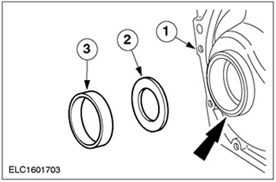
19. Using the special tool, remove the differential bearing outer race and measuring shim.
20.
CAUTION: Spring washers must be installed so that the inner raised sections of both washers touch.
Install the measured adjusting shim.
- 1. Install spring washers.
- 2. Install the required adjusting shim.
- 3. Install the inner bearing ring.
- Using a suitable punch, lock the inner bearing race.
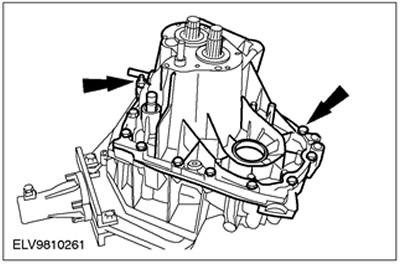
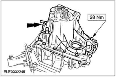
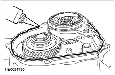
21. Apply sealant to the inner edge of the mating surface of the transmission housing in the block with the driving axle.
22. Assemble the gearbox housing in block with the drive axle and tighten the bolts.
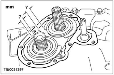
23.
NOTE: Install new input and output shaft snap rings.
Raise the primary and secondary shafts slightly and install the retaining rings.
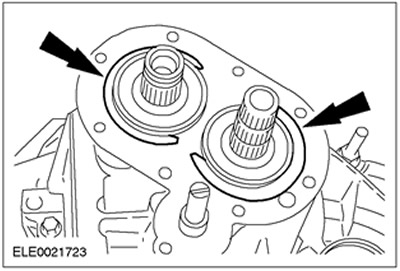
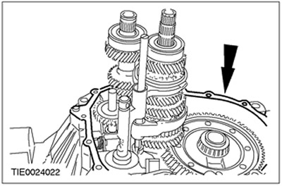
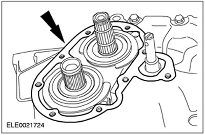
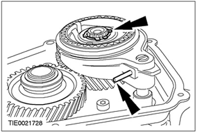
24.
CAUTION: Make sure the snap rings are installed in the correct position. Failure to follow this instruction may result in damage to the 5th gear housing.
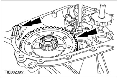
Rotate the retaining rings to the position shown.
25.
NOTE: Install a new 5th gear housing gasket.
Install the 5th gear housing gasket.
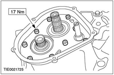
26.
NOTE: Install new 5th gear housing mounting bolts.
Install the 5th gear housing.
27. Remove the gearbox in block with the drive axle from the assembly stand.
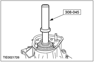
28.
NOTE: The transaxle housing must not contact the press table. Provide support for the input shaft splines.
Using the special tool and a suitable press, install the 5th gear gear
29. Install the gearbox in block with the drive axle on the assembly stand.
30.
NOTE: Install a new 5th gear snap ring.
Install the 5th gear retaining ring.
- 1. Install the retaining ring on the special tool.
- 2. Install the special tool and press the retaining ring.
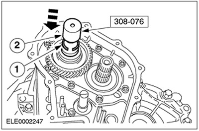
31.
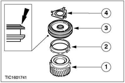
NOTE: Align the gear synchronizer position with the marks.
Assemble the 5th gear synchronizer.
- 1. Install the 5th gear.
- 2. Install the synchronizer ring.
- 3. Install the synchronizer assembly.
- 4. Install the mounting plate.
32.
NOTE: Install a new 5th gear synchronizer snap ring assembly.
NOTE: Use a new shift fork mounting pin.
Install the 5th gear synchronizer assembly and gear selector fork.
- Install the pin.
- Install the retaining ring.
33. Apply sealant evenly to the inner edge of the 5th gear housing mating surface.
34. Install the 5th gear housing cover.
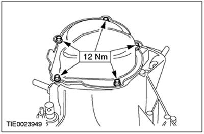
35.
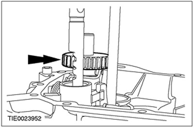
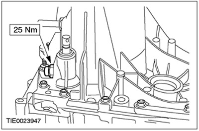
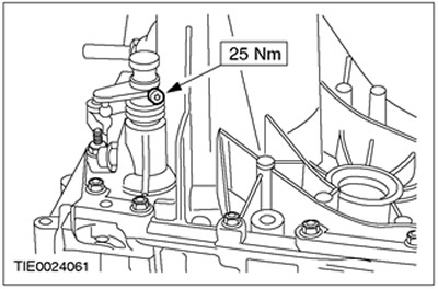
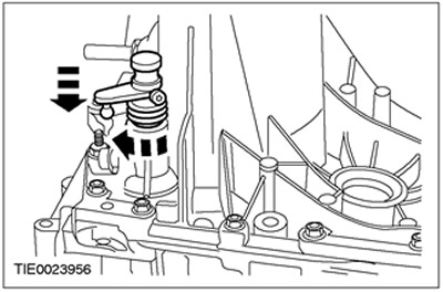
NOTE: Make sure the gear selector shaft is in neutral position.
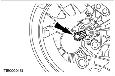
The correct installation position for the gear selector shaft locking mechanism is shown.
36.
NOTE: Make sure the gear selector shaft is in neutral position.
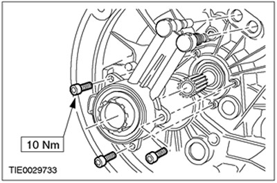
Install the gear selector shaft locking mechanism. Apply sealant to the threads.
37. Install the selector lever. Install the cover.
38. Engage 5th gear.
- Turn the selector shaft clockwise until it stops and push the shaft inward.
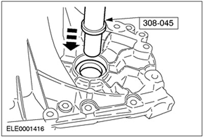
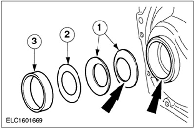
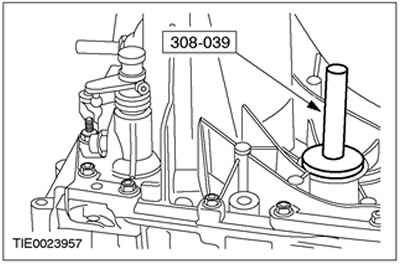
39.
NOTE: Install new axle shaft oil seals.
Using the special tools, install the oil seals on both axle shafts (left side shown).
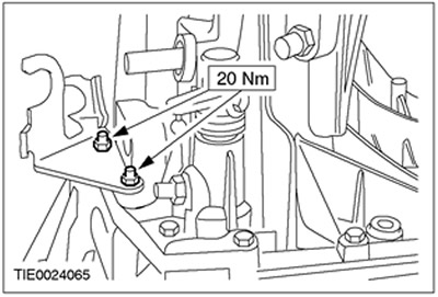
40. Install the gear shift cable support bracket.
41.
NOTE: Install a new snap ring.
Install the gear shift lever.
- 1. Install the retaining ring.
- 2. Install the protective cover.
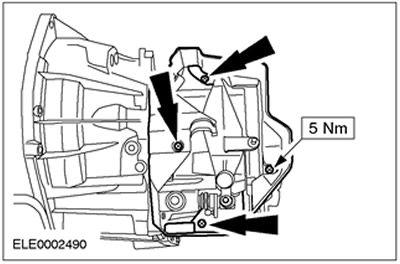
42. Install the gear selector mechanism cover.
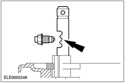
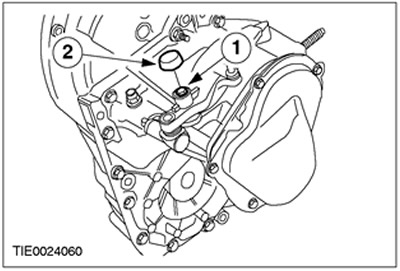
43. Install the vehicle speed sensor (VSS) (if equipped).
- 1. Press the VSS sensor.
- 2. Install the pin.
44.
CAUTION: Using suitable tape, cover the input shaft splines to prevent damage to the input shaft oil seal.
Install the input shaft oil seal.
45.
CAUTION: If brake fluid comes into contact with the paintwork, the affected area must be immediately washed with cold water.
CAUTION: Do not apply grease to the clutch slave cylinder components.
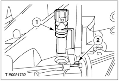
Install the clutch slave cylinder.
46. Remove the adhesive tape from the input shaft splines.
47. Apply a thin layer of high-temperature grease to the splines of the input shaft.
For more information, please visit the website: Fordbook.ru