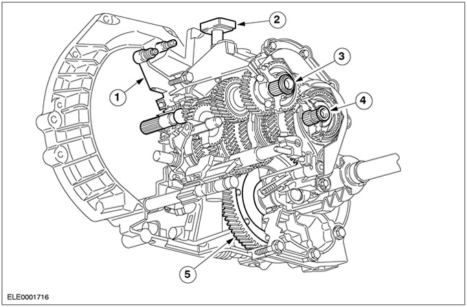
General form
| Pos. | Spare Part No | Name |
| 1 | clutch slave cylinder | |
| 2 | Gearbox breather | |
| 3 | input shaft | |
| 4 | output shaft | |
| 5 | Differential |
The iB5 manual transaxle used in the Focus is the so-called "twin shaft gearbox". Its design has been modified and now it uses a cable drive mechanism for the first time.
The aluminum gearbox housing consists of two sections. The rigidity of the crankcase is increased due to the inclusion of reinforcing ribs in its design. Crankcase sections are supplied in pairs and cannot be replaced individually. The clutch is hydraulically driven.
On a two-shaft gearbox, the gears of all gears are in constant mesh (except reverse gear). In each gear, the required gear ratio is provided by a pair of gears.
When reverse gear is selected, the direction of rotation of the output shaft is changed by using an intermediate gear.
All gears have a circular tooth, synchronized (except reverse gear) and mounted on plain bearings.
First and second gears have double synchronizers.
The iB5 manual transmission is filled with 2.5 liters of synthetic transmission fluid, specification WSD-M2C200-C. The filling level is 10-15 mm below the lower edge of the control hole. There is no need to change the transmission fluid.
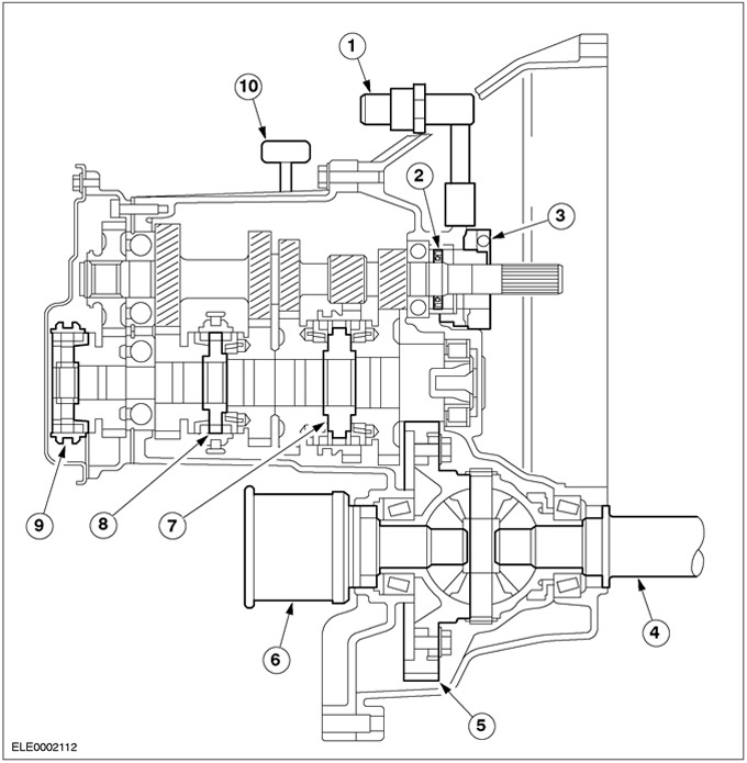
Elements of a manual transmission in a block with a drive axle iB5
| Pos. | Spare Part No | Name |
| 1 | Quick coupling | |
| 2 | Oil seal (access outside) | |
| 3 | Clutch slave cylinder with clutch release bearing (cannot be replaced separately) | |
| 4 | Intermediate shaft front drive axle | |
| 5 | Cylindrical spur gear | |
| 6 | Tripod body ("tripod") | |
| 7 | Synchronizer 1/2 gear | |
| 8 | Synchronizer 3/4th gear | |
| 9 | Synchronizer 5th gear | |
| 10 | Gearbox breather |
In the neutral position, none of the gears is connected to the output shaft through the corresponding synchronizers. Primary torque is not transmitted to the differential.
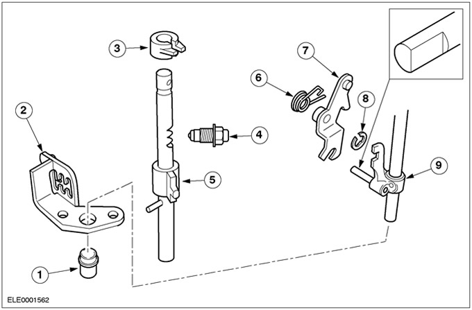
Internal shift mechanism
| Pos. | Spare Part No | Name |
| 1 | 5th/Reverse Select Rod Guide | |
| 2 | Gear selector | |
| 3 | Shift Stop Bushing | |
| 4 | Mechanism of blocking of a shaft of a choice of transfers | |
| 5 | Shaft of a choice of transfers | |
| 6 | Return spring for reverse gear selector lever | |
| 7 | Lever for selecting reverse gear | |
| 8 | Retaining ring | |
| 9 | 5th/Reverse selector rod |
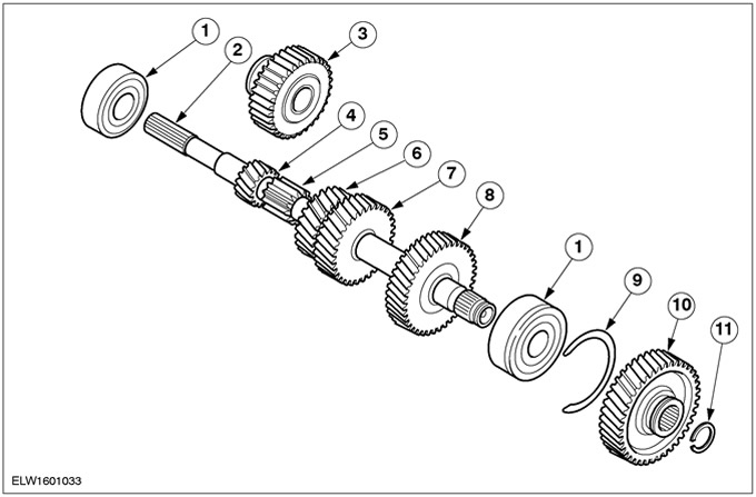
Input shaft
| Pos. | Spare Part No | Name |
| 1 | ball bearing | |
| 2 | input shaft | |
| 3 | Reverse intermediate gear | |
| 4 | 1st gear | |
| 5 | Reverse gear | |
| 6 | 2nd Gear | |
| 7 | 3rd gear | |
| 8 | 4th gear | |
| 9 | Retaining ring | |
| 10 | 5th gear | |
| 11 | Retaining ring |
Output shaft
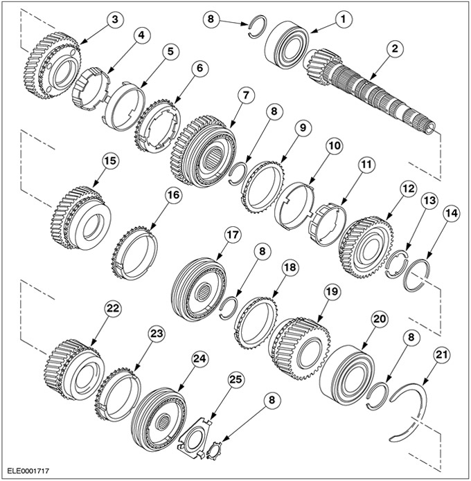
| Pos. | Spare Part No | Name |
| 1 | Roller bearing | |
| 2 | output shaft | |
| 3 | 1st gear | |
| 4 | Synchronizer inner ring | |
| 5 | Tapered synchro ring | |
| 6 | Synchronizer outer ring | |
| 7 | Synchronizer 1/2 - th gear with reverse gear | |
| 8 | Retaining ring | |
| 9 | Synchronizer outer ring | |
| 10 | Tapered synchro ring | |
| 11 | Synchronizer inner ring | |
| 12 | 2nd Gear | |
| 13 | Retaining rings | |
| 14 | Retaining ring | |
| 15 | 3rd gear | |
| 16 | Synchronizer ring 3rd gear | |
| 17 | Synchronizer 3/4th gear | |
| 18 | Synchronizer ring 4th gear | |
| 19 | 4th gear | |
| 20 | ball bearing (closed on both sides) | |
| 21 | Retaining ring | |
| 22 | 5th gear | |
| 23 | Synchronizer ring 5th gear | |
| 24 | Synchronizer 5th gear | |
| 25 | lock bar |
Double synchronizer
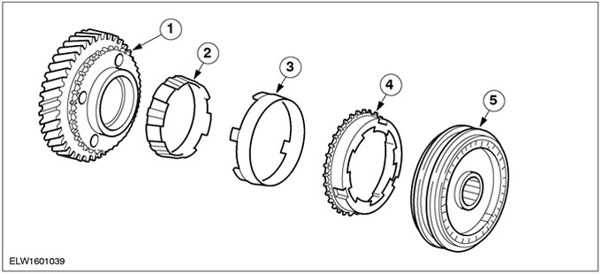
| Pos. | Spare Part No | Name |
| 1 | Gear | |
| 2 | Synchronizer inner ring | |
| 3 | Tapered synchronizer ring | |
| 4 | Synchronizer outer ring | |
| 5 | Synchronizer hub |
Double synchronizer
First and second gears have double synchronizers. By using a second synchronizer ring, the effective synchronizer surface is significantly increased compared to a single synchronizer. Double synchronization gives a significant improvement in the quality of gear shifting.
Dual synchronizers include an inner synchronizer ring, a tapered ring, an outer synchronizer ring, and a synchronizer hub.
The conical surface of the gear is no longer used. Synchronization occurs through the use of synchronizer rings and a conical ring that is attached to the gear.
Differential
The main elements of the differential include:
- Cylindrical spur gear
- Differential box with two tapered roller bearings
- Differential satellites
- Side gears
The gearbox and differential are enclosed in a two-section aluminum crankcase, which is flanged to the engine. The axle shafts of the drive axle are splined.
Primary torque is transmitted to the differential via a spur gear that is bolted to the differential case.
The differential box contains differential satellites mounted on one axle, as well as side gears having a splined connection with the axle shafts of the front drive axle.
If the front wheels have different speeds (e.g. when turning), the side gears can move the pinions of the differential.
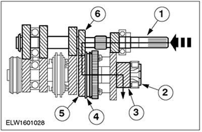
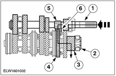
Neutral gear
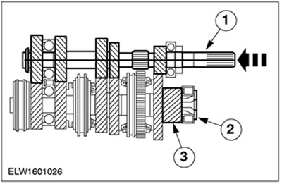
| Pos. | Spare Part No | Name |
| 1 | input shaft | |
| 2 | output shaft | |
| 3 | output gear |
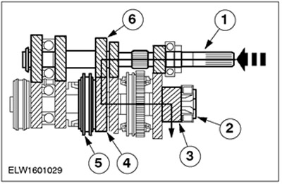
First gear
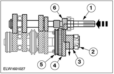
| Pos. | Spare Part No | Name |
| 1 | input shaft | |
| 2 | output shaft | |
| 3 | output gear | |
| 4 | 1st gear | |
| 5 | Synchronizer 1/2 - th gear | |
| 6 | 1st gear |
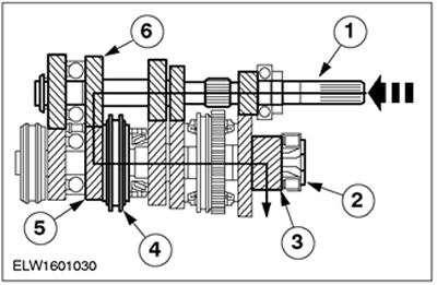
Second gear
| Pos. | Spare Part No | Name |
| 1 | input shaft | |
| 2 | output shaft | |
| 3 | output gear | |
| 4 | Synchronizer 1/2 - th gear | |
| 5 | 2nd Gear | |
| 6 | 2nd Gear |
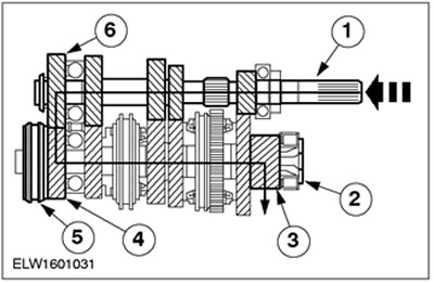
Third gear
| Pos. | Spare Part No | Name |
| 1 | input shaft | |
| 2 | output shaft | |
| 3 | output gear | |
| 4 | 3rd gear | |
| 5 | Synchronizer 3/4th gear | |
| 6 | 3rd gear |
Fourth gear
| Pos. | Spare Part No | Name |
| 1 | input shaft | |
| 2 | output shaft | |
| 3 | output gear | |
| 4 | Synchronizer 3/4th gear | |
| 5 | 4th gear | |
| 6 | 4th gear |
Fifth gear
| Pos. | Spare Part No | Name |
| 1 | input shaft | |
| 2 | output shaft | |
| 3 | output gear | |
| 4 | 5th gear | |
| 5 | 5th gear synchronizer | |
| 6 | 5th gear |
Reverse gear
| Pos. | Spare Part No | Name |
| 1 | input shaft | |
| 2 | output shaft | |
| 3 | output gear | |
| 4 | Reverse gear | |
| 5 | Reverse gear | |
| 6 | Reverse intermediate gear |
The reverse gear is driven by the input shaft. Its purpose is to change the direction of rotation of the secondary shaft when the reverse gear is engaged.
The intermediate reverse gear is supported by a needle bearing located on the intermediate axle and a bearing block.
The gear selection locking mechanism and the gear selection pin are fixed on the bushing in the gear selection housing. They use a spring-loaded ball to keep the selected gear engaged until another gear is selected.
The gear selector lock mechanism has three different positions.
Visitor comments