Contents: Removal ↳ Manual transmission ↳ Automatic transmission ↳ All models ↳ Engine and gearbox - dismantling and… ↳
Attention: Please read the entire section, including the message at the beginning section 3, before you begin removing the engine. This section describes how to remove the engine and gearbox from the top of the engine compartment and then separate them.
Removal
1. Contact section 4 and perform the work described in paragraphs 1 through 18 inclusive.
2. Disconnect the wiring from the starter, noting the positions of the cables.
3. Apply the parking brake, then raise the front of the vehicle and support it on jack stands.
Manual transmission
4. Once under the vehicle, separate the rubber boot of the clutch release lever from the clutch housing and slide it up the cable.
5. Pull the cable out of the slot on the release lever and separate the cable sheath from the clutch housing. Remove the rubber boot from the cable.
6. Where present, release the fasteners and remove the two-piece cover covering the clutch housing (see figure 6.6).
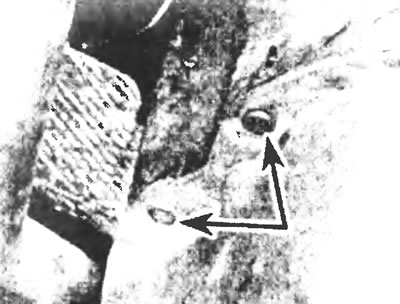
Figure 6.6. Release the fasteners (indicated by arrows) and remove the two-piece cover that covers the clutch housing.
7. Contact Chapter 7A and remove the gear shift levers according to the gearbox type.
8. Disconnect the wires from the reverse light switch on the gearbox.
9. On G and MT75 type transmissions, place a drain pan under the drain plug and drain the transmission oil. Replace the drain plug when finished.
10. Remove the propeller shaft as described in Chapter 8.
11. Unscrew the retaining bolt and remove the speedometer drive shaft pressure plate. Remove the speedometer cable from the transmission and set it aside.
12. If your vehicle is equipped with an electronic tachograph, disconnect the tachograph cable and set it aside.
13. Remove the bolt and separate the lower cover plate(s) from the clutch housing.
14. Disconnect the fuel lines from the clamps on the support bracket mounted on top of the clutch housing. Also disconnect the engine ground cable if it is secured by one of the clutch housing bolts.
15. Place a jack under the transmission to support it.
16. Unscrew the single central bolt (g or N type gearbox) or two nuts (m175 gearbox), fastening the support crossmember to the gearbox housing. Remove the two bolts on each side and remove the crossmember from under the vehicle.
Automatic transmission
17. Contact Chapter 8 and remove the driveshaft.
18. Disconnect the exhaust distribution pipe from the exhaust manifold and muffler and pull it out through the bottom of the car.
19. Disconnect the speedometer cable from the rear of the transmission. If your vehicle is equipped with an electronic tachograph, disconnect the tachograph cable and set it aside.
20. Move the gear selector lever to the "N" position.
21. Once under the vehicle, use a screwdriver to pry up the end of the control cable and separate the cable from the ball-end stud on the transmission control lever (see Figure 6.21). Unscrew the two bolts and remove the support bracket along with the cable, setting them aside
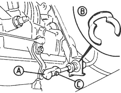
Figure 6.21. Location of the gearbox control cable: A. A stud with a ball end at the end of the cable; B. Thrust washer; C. Cable tension adjustment screw.
22. Disconnect the downshift solenoid valve wiring connector.
23. Disconnect the wiring from the starter lock switch.
24. Pull out the transmission fluid dipstick, then loosen the retaining bolt and separate the dipstick tube from the transmission. Plug the hole in the transmission that was exposed after removing the tube.
25. Wipe clean the areas around the coolant connections on the right side of the transmission, then loosen and remove the connections. Plug the exposed holes in the transmission and the ends of the pipes and set the pipes aside.
26. Jack up the transmission with a jack placed under the transmission oil pan. To prevent damage to the pan, place a block underneath it, but make sure that the transmission does not slide off under any circumstances during the following procedures.
27. Remove the single center bolt securing the support crossmember to the transmission housing and the two bolts on each side. Remove the cross member.
All models
28. Secure the engine to a suitable lift. If possible, fabricate lifting eyes to connect the hoist to the engine, making sure they are strong enough, and connect them to the front and rear of the engine at diagonally opposite points.
29. Check again that all relevant components and accessories are disconnected and put aside.
30. Raise the engine slightly to clear the engine mounts, then separate the engine mounts from both sides of the cylinder block.
31. With the help of an assistant, move the engine forward and away from the transmission while lifting it. Once the engine is separated from the transmission, carefully guide it upward and remove it from the engine compartment. Do not allow the engine to hang on the transmission input shaft at any time during the removal process (or installations) engine. On models with automatic transmission, ensure the torque converter remains engaged with the transmission. Once the engine tray is separated from the vehicle, move the power unit to the side and lower it onto a dolly. If a mobile lift is not used, the vehicle must be moved backwards and then the engine must be lowered. In this case, make sure the gearbox is well supported while moving the vehicle.
32. After removing the engine, check the mounts and replace them with new ones if they are worn or damaged. Also check the condition of all hoses and pipes (see chapter 1). Components that are usually hidden can now be properly checked and replaced at the slightest doubt regarding their condition.
Engine and gearbox - dismantling and installation
Dismantling
33. On manual transmission models, remove the two bolts and the lower clutch housing cover, if equipped.
34. Unscrew the bolts and remove the starter.
35. On models with automatic transmission, unscrew the bolt and separate the engine and gearbox retaining bracket. Working through the hole created by removing the starter, unscrew the four nuts holding the drive disk to the torque converter. If necessary, the engine crankshaft can be turned using a wrench on the groove pulley bolt to bring the torque converter retaining nuts into an accessible position.
36. Unscrew all the bolts holding the clutch and torque converter housings together, attaching the engine to the transmission.
37. With the engine properly supported, slide the gearbox back off the dowel pins, ensuring that the engine does not hang on the gearbox input shaft. On models with automatic transmission, ensure that the torque converter remains in its place on the transmission. It is advisable to support the torque converter while separating the transmission.
38. Move the transmission, free from the engine, to the side.
Installation
39. Before connecting the engine to the gearbox, apply a thin layer of high melting point lubricant to the splines of the gearbox input shaft. If the clutch has been removed, ensure the clutch disc is centered.
40. After installing the torque converter onto the transmission and engaging it with the oil pump drive, ensure that the distance between the front surface of the torque converter flange and the flange of the torque converter housing is at least 21 mm. Slightly tilt the transmission backward during installation to prevent the torque converter from falling forward. Once the transmission is fully engaged with the engine, check that the torque converter turns freely, then install the bolts securing the torque converter housing to the engine.
41. Install the remaining components and tighten all connections to the specified torque.
Installation
42. Installation is generally carried out in the reverse order of removal, but the following points must be taken into account.
43. Tighten all connections to the specified torque.
44. After installing the engine on the supports, check that there is equal play on both sides between the lower corners of the rubber mount and the installed chassis bracket.
45. Check that the mating surfaces are clean, then connect the exhaust pipe using new self-locking nuts and gasket.
46. Make sure all connections are properly and securely fastened.
47. Remove temporary plugs or caps from fuel lines before connecting them properly and securely.
48. Connect and adjust the accelerator cable as described in Chapter 4. Details of installation of intake manifold and air filter are also given in this Chapter.
49. Replace the coolant hoses with new ones (or fixing clamps), if they are in bad condition.
50. Contact Chapter 6 for details when connecting the clutch cable.
51. On vehicles with power steering or air conditioning, install and adjust the drive belt(s) as described in Chapter 1.
52. Install the driveshaft as described in Chapter 8.
53. On models with automatic transmission, adjust the control and downshift cables as described in Chapter 7B.
54. Once the engine is completely installed, make sure all hoses are connected and then add engine oil, transmission fluid and coolant as described in Chapter 1.
55. Once completed, start the engine in accordance with section 23.