Contents: Removal ↳ Installation ↳
Note: New driveshaft coupling flange bolts will be required during installation.
Removal
Gearboxes without overdrive
1. Block both front wheels, jack up the rear of the car and place it on supports.
2. Mark the position of the rear universal joint and the final drive connecting flanges relative to each other.
3. Unscrew the bolts securing the propeller shaft to the main transmission connecting flange (see figure 3.3). Hold the shaft still with a long screwdriver inserted into the crosspiece of the joint. Install the shaft on the support after disconnecting the flanges.
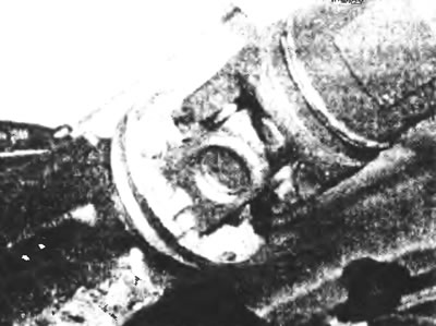
Figure 3.3. Bolts of the rear universal joint of the propeller shaft at the connecting flange of the main transmission.
4. If the front of the driveshaft is attached to the transmission by a coupling flange, mark the position of the joint and the transmission coupling flange relative to each other, then unscrew the retaining bolts while holding the driveshaft stationary as before (see figure 3.4).
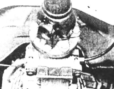
Figure 3.4. Bolts of the front universal joint of the propeller shaft and the connecting flange of the gearbox.
5. Supporting the front and rear sections of the driveshaft, unscrew the two center support retaining bolts from the underbody of the vehicle (see figure 3.5).
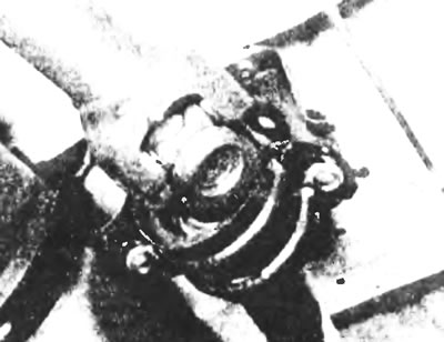
Figure 3.5. Central support of the cardan shaft.
6. Lower the propeller shaft relative to the connecting flanges and the central bearing mount, and remove it from the vehicle. If a front sliding joint is used, pull it rearward to disengage it from the transmission output shaft; to prevent oil from spilling from the transmission, you can insert a chamfered plastic cup into the oil seal (see Figure 3.6). You can also use a plastic bag secured with a rubber band to the transmission.
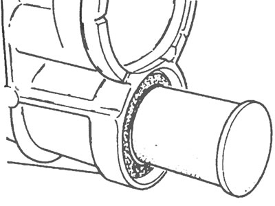
Figure 3.6. Plastic cup to prevent transmission oil spillage inserted into the oil seal.
Overdrive transmissions
7. Block both front wheels. Jack up the rear of the car and support it on supports.
8. Mark the position of the front universal joint flange and the overdrive flange relative to each other, then loosen the fixing bolts. Hold the shaft still with a long screwdriver inserted into the crosspiece of the joint. Support the shaft on the support after separating the flanges.
9. Mark the position of the rear section of the shaft relative to the front, on the splined joint just behind the center support (see figure 3.9).
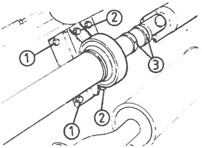
Figure 3.9. Cardan shaft center support and splined connection (overdrive gearboxes): 1. Center support bracket bolts, 2. Center support bolts, 3. Front and rear propeller shaft alignment marks at the splined joint.
10. Mark the position of the rear universal joint and connecting flanges relative to each other, then unscrew the retaining bolts while holding the propeller shaft stationary as before.
11. Lower the rear section of the driveshaft relative to the coupling flanges, slide it rearward to disengage it from the splined joint, and remove it from under the vehicle.
12. Unscrew the two center support retaining bolts and remove the front section of the propeller shaft from under the vehicle.
Installation
Transmissions without overdrive
13. If a front end sliding joint is used, remove the cup or bag used to prevent oil spillage, then lubricate the rear transmission oil seal with multi-purpose lubricant. Guide the splined end of the driveshaft onto the transmission driven shaft, being careful not to damage the oil seal.
14. At the point where the propeller shaft is secured by the front coupling flange, align the marks made during removal, then secure the coupling flanges using new bolts to the specified tightening torque. If the driveshaft has a vibration damper, the yellow mark on the damper and the balancing weights on the shaft must be aligned.
15. Raise the center of the driveshaft and loosely install the two center support retaining bolts. Do not tighten the bolts yet.
16. Raise the rear of the propeller shaft, align the coupling flange marks made during removal and secure the flanges using new bolts to the specified torque.
17. If a constant velocity joint is installed behind the center support, ensure that the center support is installed perpendicularly and without deformation, then lower the vehicle to the ground. Tighten the center support retaining bolts to the specified torque with the vehicle on its wheels in an unladen condition.
18. On vehicles with a constant velocity joint installed after the center support, ensure that the rear axle hangs freely. Move the center support and constant velocity joint back as far as possible, make sure the center support rubber cushion is not deformed, then tighten the center support fixing bolts to the specification torque.
19. On vehicles with a splined front driveshaft and transmission connection, check and, if necessary, top up the transmission fluid to the required level as described in Chapter 1.
Overdrive transmissions
20. Guide the front propeller shaft into the center support and loosely install the two center support retaining bolts. Don't tighten them yet.
21. Align the marks on the front universal joint flange and the overdrive flange made during removal, then secure the connecting flanges using new bolts to the specified tightening torque.
22. Generously lubricate the ends of the front and rear splined driveshaft sections with multi-purpose lubricant. Align the marks made during removal and insert the splined end of the rear support into the housing. If a new one is installed (unmarked) front or rear sections of the driveshaft, make sure the universal joint crosses are at 90° to each other as shown in the figure (see Figure 3.22).
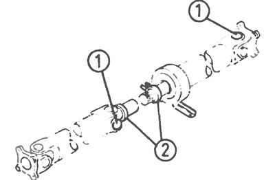
Figure 3.22. Aligning the cardan joint of the front and rear sections of the cardan shaft: 1. Crosspieces of the universal joint, installed with a 90 degree rotation relative to each other, 2. Installation marks
23. Raise the rear section of the propeller shaft, align the marks on the connecting flange made during removal, and secure the flanges using new bolts to the specified tightening torque.
24. Make sure that the center support is installed without distortion or deformation, then lower the car to the ground. Tighten the center support retaining bolts to the specified torque with the vehicle in an unladen position on its wheels.
25. Upon completion, lubricate the driveshaft splines through the grease fittings until lubricant comes out of the breather hole in the plug on the splined race side.