2. Remove the locking tab from the universal joint mounting bolt, then loosen the bolt using a suitable flat-end wrench (see Figure 5.2).
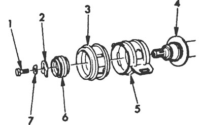
Figure 5.2. Details of the middle support of the cardan shaft: 1. Bolt, 2. U-washer, 3. Rubber cushion, 4. Cardan shaft, 5. Housing, 6. Ball bearing, 7. Lock washer.
3. Remove the U-shaped washer from under the bolt head, then insert a screwdriver or metal rod between the bolt head and the universal joint to separate the two sections of the drive shaft (see Figure 5.3).
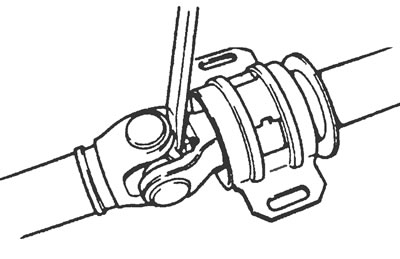
Figure 5.3. Separating the cardan shaft sections.
4. Remove the bearing housing with the rubber cushion.
5. The bearing can now be removed from the driveshaft with a suitable puller (see Figure 5.5).
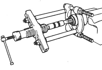
Figure 5.5. Using a puller, remove the bearing from the driveshaft.
6. To replace the rubber cushion in the bearing housing, bend back the 6 metal locking tabs. Then remove the old rubber pad. Insert the new rubber cushion together with the balls into the housing. Make sure the rubber pad fits into the groove in the housing.
7. Once the rubber pad and bearing are installed, bend the metal retaining tabs back into place.
8. Install the cardan shaft on the end and support it with a pipe of a suitable diameter. Drive the middle support into place with a hammer until it stops, using a pipe (see Figure 5.8).
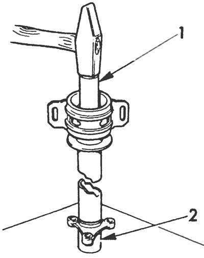
Figure 5.8. Installation of the middle support.
9. Install the bolt together with the new locking tab, but do not tighten it yet.
10. Reinstall the universal joint onto the shaft, aligning the guide groove and the Double Wide recess, and press them together (see Figure 5.10).
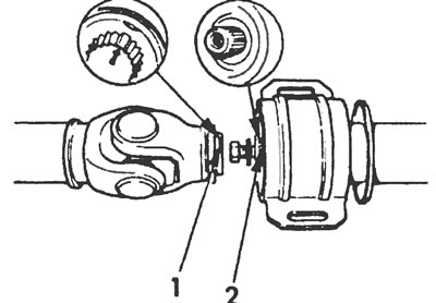
Figure 5.10. Installation marks on the cardan shaft and joint.
11. Install the U-shaped washer with the tab side facing the bearing, then tighten the universal joint retaining bolt to specification.
12. Using a long rod or suitable punch, tap the locking tab and tighten the bolt.
13. Install the propeller shaft as described in Section 3 or 4.