Contents: Removal ↳ Installation ↳
Note: The procedures for removing and installing the rear axle are described below, piece by piece. If required, the entire axle, including the wheels and rear springs, can be removed as a single unit; to do this, the vehicle must be raised to a greater height (so that when removing the unit the body does not interfere with the wheels). In the latter case, you must follow the instructions below, ignoring references to removing the wheels and springs from the axle. Please contact Chapter 10 for details on removing springs.
Removal
1. Make sure the vehicle is unloaded, then block the front wheels, remove the wheel cover and loosen the rear wheel nuts. Remember that on pre-1992 models with six-stud wheels, the left wheel nuts have left-hand threads - that is, they unscrew clockwise.
2. Jack up the rear of the vehicle and support it from the frame side in front of the rear springs. Support the weight of the rear axle with a jack placed under the differential housing.
3. Unscrew the wheel nuts and remove the rear wheels. On type "H" axles, mark the position of the rear wheels relative to the drum or hub.
4. Mark the relative positions of the pinion and drive flanges of the driveshaft for reinstallation, then remove the four bolts and remove the driveshaft, supporting it on supports. Please note that new bolts will be required to install the flange.
5. Disconnect the rear brake pipe from the hydraulic brake system flexible hose, then remove the retaining spring clip and remove the hose from the support bracket. After disconnecting, close the lines with plugs to prevent dirt from entering and liquid from leaking. Note that if a load-sensing valve is installed on the rear brakes, the upper end of the adjusting spring must be disconnected by removing the head pin. On later models, slide the lower end of the adjusting spring out of the slot in the bridge bracket after removing the retaining clip from the top edge of the bracket (see figure 8.5, a, b).
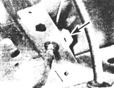
Figure 8.5,a. Remove the retaining spring clamp and remove the hose from the support bracket.
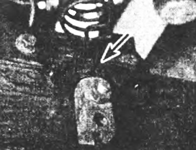
Figure 8.5,b. On later models, pull the lower end of the adjusting spring out of the slot in the bridge bracket.
6. After unhooking the parking brake release spring, pull out the mounting clip with the pin (with a head and a hole for a cotter pin), to disconnect the parking brake cable at the equalizer joint (see Figure 8.6). Release the two outer cable bushings in the mounting bracket and also remove the exhaust section at the rear of the vehicle to bypass the parking brake cable when removing the axle.
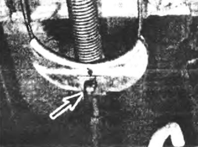
Figure 8.6. Remove the retaining clip with pin (with a head and a hole for a cotter pin), to disconnect the parking brake cable at the equalizer joint.
7. Disconnect the parking brake cable support brackets from the upper shock absorber mount.
8. On vehicles equipped with ABS, disconnect the wheel speed sensor wiring.
9. Unscrew the retaining nuts and bolts and separate the rear shock absorbers from the axle (see figure 8.9).
Figure 8.9. Loosen the retaining nuts and bolts and remove the rear shock absorbers from the axle.
10. Make sure the bridge assembly is securely supported in the center by a jack. Have an assistant watch the bridge from both sides as you lower it to the floor.
11. Unscrew the retaining nuts, U-bolts and fasteners on each side (see Figure 8.11). Make sure all axle fasteners are disconnected, then carefully lower the axle assembly and remove it from under the vehicle.
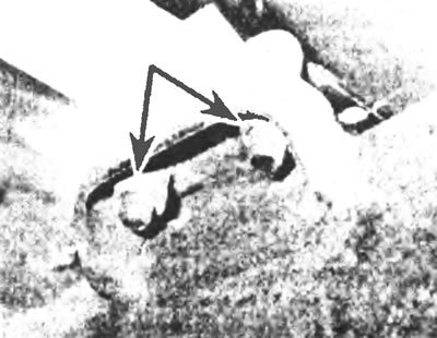
Figure 8.11. Loosen the retaining nuts, U-bolts (step bolts) and fasteners on each side.
Installation
12. Installing the bridge is basically the reverse procedure of removing it, but the following points should be noted:
- a) When installing, replace all self-locking nuts and spring washers;
- b) When raising the bridge on each side, align the hole located in the bridge with the central bolt of the spring;
- c) Tighten the U-bolts (stepladders) of the rear axle to the specified tightening force;
- d) When connecting the propeller shaft to the pinion flange, ensure that the marks made during removal are aligned and that new mounting bolts are used and tightened to the specified torque;
- d) Contact Chapter 9 for details on connecting brake system components. Top up and bleed the brake hydraulic system as also described in Chapter 9;
- e) If the bridge was disassembled, then add oil to the required level, as described in Chapter 1.
The article was taken in its entirety from the specified website: www.FordBook.ru