Please note: Rear hub fixing methods have changed frequently over the course of production. Review all procedures before you begin work and make sure you have all the tools necessary for the job. Use extreme caution when removing and installing hub nuts as they are tightened to extremely high torque (especially on the latest models). In any case, new hub nuts should be used during installation.
Caution: Due to the extremely high tightening torque of the rear hub nut (especially on the latest models), place stands under the rear axle so that additional stands can be added, and use extreme caution when removing and installing the hub nuts. When working, use only the correct sockets for the type of nut and ensure you have the correct nut removal tool and a torque wrench capable of tightening them to the correct torque (see Specifications) during installation. Refer this work to a dealer or suitably equipped garage if the procedures are unclear or if the required tools are not available.
Removal
Mod. 51A and 53
1. Contact Section 9 and remove the axle shaft on the side you are interested in.
2. Bend the washer tongue away from the hub lock nut and unscrew the lock nut. After removing the washer, unscrew the hub nut (see Figure 11.2).
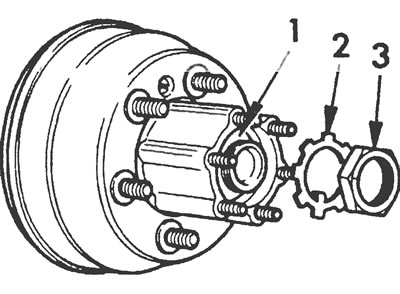
Figure 11.2. Type "G" bridge (mod. 51A and 53): hub nut (1), lock washer (2) and lock nut (3).
3. After releasing the parking brake, remove the hub together with the brake drum and outer bearing race, which is removed after removing the hub and drum. On vehicles equipped with ABS, take care not to damage the wheel speed sensor ring.
Mod. 51 - models from 1992
4. Refer to Section 9 and remove the axle shaft on the side you are interested in.
5. After removing the axle shaft, pull out the spacer ring installed between the bearing and the rear axle housing.
6. The hub is secured with a twelve-sided nut, which is tightened to an extremely high torque. To remove and install the nut, you will need a 21/4-inch AF end head. The left hub nut has a left thread, and the right hub nut has a right thread. Left-hand threaded nuts can be identified by a marking groove running around the circumference of the nut (see Figure 10.5).
7. Using a socket and a long extension rod, unscrew the hub nut.
8. Remove the hub, taking care not to damage the wheel speed sensor ring on vehicles equipped with ABS.
Major repairs
Mod. 51A and 53
9. Clean and inspect the hub as described in paragraph 12 of the previous Section (see Figure 11.9).
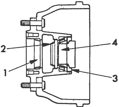
Figure 11.9. Axle hub type "C "(mod. 51A and 53): 1. Outer ring of the outer tapered roller bearing, 2. Outer seal, 3. Inner seal, 4. Inner ring of the inner tapered roller bearing.
10. For disassembly, use the front and back sides of the hub flange as a support (but not the brake drum or wheel studs) so as not to damage the timing ring on vehicles with ABS.
11. Before removing the old oil seals, record their positions and installation depths in the hub. There are special Ford push-in tools designed to accurately install new seals, but pre-made matching sockets or pieces of pipe can be used if the correct installation position of the seals is known.
12. Using a soft metal drift or a pipe of suitable diameter, press out the outer oil seal, inner tapered roller bearing race and inner oil seal.
13. Press out the outer rings of the inner and outer tapered roller bearings.
14. Clean the hub with a fine file, removing any nicks or burrs caused by removing the outer bearing races.
15. To reassemble the hub, support it on the front side inside the brake drum (but not on the drum directly) so that the pins stick up.
16. Press the new outer tapered roller bearing outer race into the hub until it contacts the hub flange.
17. Turn the hub with the drum over with the studs down and place it on the supports in this position.
18. Press the new inner tapered roller bearing outer race into the hub until it contacts the hub flange.
19. With the seal contact lip facing downwards, press the outer oil seal into the outer bearing race to the installation position noted during removal.
20. Generously lubricate the inner roller bearing and install it into place in the outer bearing race.
21. Press the inner oil seal into the hub to the installation position noted during removal.
Mod. 51 - models from 1992
22. The procedure for major repairs is similar to that described above for the type "H" bridge (see paragraphs 12 through 18 of Section 10).
Installation
Mod. 51A and 53
23. Once the hub is assembled, lubricate the inner and outer oil seals and inner bearing with grease and install the hub and drum onto the axle.
24. Lubricate the outer bearing and position it inside the outer bearing outer race in the hub.
25. Thread the hub nut and tighten it to the specified torque, rotating the hub and drum in both directions to seat the bearing (see Figure 11.25).
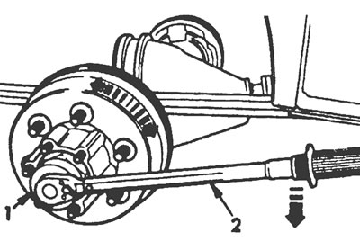
Figure 11.25. Tightening the "G" type axle hub nut (mod. 51A and 53): 1. Socket head, 2. Torque wrench.
26. Loosen the hub nut approximately 180° (half a turn), install the lock washer, positioning its tab under the hub nut.
27. Thread the hub lock nut and tighten it to the specified torque.
28. Check the hub bearing play with a suitable dial indicator (see Figure 11.28). If necessary, adjust the hub bearings to achieve the specified clearance. When the bearing play is satisfactory, bend the tabs of the lock washer inward over the hub nut and outward over the jam nut.
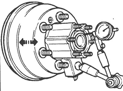
Figure 11.28. Checking the play of the hub bearing of the "G" type axle (mod. 51A and 53) using a pointer indicator.
29. Install the axle shaft as described in Section 9.
Mod. 51 - models from 1992
30. Once the hub is assembled, lubricate the contact lips of the oil seal with grease, then carefully slide the hub onto the axle, using the axle shaft as a guide. Remove the axle shaft again.
31. Screw on the new hub nut, referring to the notes made earlier regarding the identification of left and right hand nuts.
32. With the rear axle securely supported, tighten the hub nut to the specified torque, then install the spacer ring in front of the bearing
33. Install the axle shaft as described in Section 9.
[The text of the article was copied from the website: fordbook]