Contents: Removal ↳ Installation ↳
Attention: Please read the entire section, including the message at the beginning section 3 before you begin removing the engine. This section describes how to remove the engine separately from the transmission through the top of the engine compartment.
Removal
1. Disconnect the negative battery cable.
2. Contact Chapter 1 for details and drain the coolant and engine oil. Reinstall the oil pan drain plug when finished to prevent any oil remaining in the engine from escaping.
3. Contact Chapter 11 for details and remove the hood. Place it in a safe place where it will remain undamaged.
4. Contact Chapter 4 and remove the air filter unit.
5. Release the retaining clips and separate the coolant hoses from the thermostat housing, the lower hose from the radiator and water pump, and the heater hoses from the engine and bulkhead. Please note that coolant will spill when separating the hoses. Note the direction of the hoses, then set them aside.
6. After disconnecting the hoses, unscrew the two screws and remove the expansion tank of the cooling system.
7. Contact Chapter 11, and remove the front grille and front bumper.
8. Contact Chapter 3 and remove the radiator together with the upper support cross member.
9. Separate the air intake pipe from the turbocharger flange and from the intake manifold. Remove the gasket from the turbocharger side.
10. Disconnect the vacuum hoses at the following locations (see Figure 5.10).
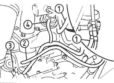
Figure 5.10. Disconnect the vacuum hoses between: 1. Vacuum regulator - vacuum pump; 2. Throttle body - manifold pressure sensor; 3. Turbocharger wastegate - vacuum regulator; 4. EGR valve - vacuum regulator.
11. On vehicles with power steering (refer to Chapter 1) remove the power steering pump drive belt. Remove the pump mounting bracket from the cylinder block and set it aside from the engine.
12. On cars with air conditioning (refer to Chapter 1) remove the air conditioning compressor drive belt. Separate the compressor from the engine and set it aside. Do not disconnect the air conditioning system hoses.
13. On models from 1995 with exhaust gas intercooling (EGP), remove the radiator as described in Chapter 4.
14. Disconnect the fuel supply lines from the fuel filter and the fuel return line from the high pressure fuel pump. Plug or cap all open connections.
15. Disconnect the fuel supply hoses from the fuel pump. If using quick release couplings on the fuel lines, release the clamps on the couplings, pinch them together, and gently pull them toward you to remove the couplings. Use a rag to soak up any spilled fuel. Plug the hose to prevent fuel from spilling and dirt from getting inside.
16. Depending on the type of alternator, either disconnect the multi-pin plug or remove the plastic cover and unscrew the terminal nuts. Disconnect the alternator wires, marking their location.
17. Unscrew the union nut and separate the vacuum pipe from the rear of the brake booster vacuum pump located on the alternator.
18. Noting their location, disconnect the plug connectors from the following components (see Figure 5.18).

Figure 5.18. Disconnect the electrical connections of the following components: 1. Cable bracket on the intake manifold; 2. Multi-pin plug of the EPIC system on the high-pressure fuel pump; 3. Coolant temperature gauge measuring transducer; 4. Lucas EPIC coolant temperature sensor; 5. Low oil pressure sensor; 6. Cylinder block ground wire; 7. Fuel filter water separator; 8. Crankshaft position and speed sensor; 9. Pre-heating system torch plug (on some models).
19. Remove the starter as described in Chapter 5.
20. Apply the parking brake, then raise the front of the vehicle and support it on stands.
21. On 1995 and later models, remove the two bolts and nuts securing the steering gear to the crossmember, then pull the assembly forward and down as far as it will go.
22. Disconnect the exhaust pipe from the manifold and the front flange of the muffler. Remove the pipe and take out the flanges.
23. Once under the vehicle, separate the rubber boot of the clutch release lever from the clutch housing and slide it up the cable.
24. Pull the cable out of the groove on the release lever and separate the cable sheath from the clutch housing. Remove the rubber boot from the cable.
25. Unscrew the two bolts and remove the lower clutch housing cover.
26. On vehicles with a manual transmission MT75, disconnect the wires from the reversing light switch.
27. Unscrew the lower nut and washer from both engine mounts.
28. Unscrew the lower bolts connecting the clutch housing to the engine, which are only accessible from below, then lower the car to the ground.
29. Secure the engine to a suitable lift. If possible, fabricate lifting eyes to connect the hoist to the engine, making sure they are strong enough, and connect them to the front and rear of the engine at diagonally opposite points.
30. Place a suitable jack under the transmission and jack it up slightly without lifting it.
31. Remove the remaining bolts connecting the engine to the transmission, noting that on later models, the top bolts also secure the fuel line support bracket. Remove the fuel line clamps from the support bracket.
32. Check again that all relevant components and devices are disconnected and put aside.
33. With the help of an assistant, move the engine forward and away from the transmission while lifting it. Once the engine is separated from the transmission, carefully guide it upward and out of the engine compartment. Do not allow the engine to hang on the transmission input shaft during removal (or installations) engine. On models with automatic transmission, ensure the torque converter remains engaged with the transmission. Once the engine tray is separated from the vehicle, move the power unit to the side and lower it onto a dolly. If the trolley is not in use, the vehicle must be moved backwards and then the engine must be lowered. In this case, make sure the gearbox is well supported while moving the vehicle.
34. After removing the engine, check the mounts and replace them with new ones if they are worn or damaged. Also check the condition of all hoses and pipes (see chapter 1). Components that are usually hidden can now be properly checked and replaced at the slightest doubt regarding their condition. Also, don't forget about the possibility of a major clutch overhaul (see Chapter 6). It is considered beneficial to replace the clutch with a new one whenever a major engine overhaul is carried out. Also check the condition of all components (types of gearbox seals), damaged during removal, and replace those that are damaged or worn with new ones.
Installation
35. Installation is generally carried out in the reverse order of removal. Refer to paragraphs 34 through 46 section 4 for additional information and individual points to be noted during installation.
[For details, please visit the website: FORDBOOK.RU]