Contents: General information ↳ Location of serial number and engine… ↳ Cylinder head cover ↳ Camshafts ↳ Cylinder head ↳ Cylinder head gasket ↳ Cylinder block ↳ Crank mechanism ↳ Pistons ↳ Oil pan ↳ Valve mechanism ↳ Timing Belt Tensioner with Cam ↳ Timing Belt Tensioner with Groove ↳ Crankshaft pulley/vibration damper ↳
General information
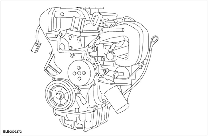
The Focus is equipped with Zetec-SE engines with a displacement of 1.4 liters and a power of 55 kW/75 hp and a displacement of 1.6 liters and a power of 74 kW/100 hp, respectively.
The Zetec-SE engine is an all-aluminium construction. Both engine variants meet the stringent EEC-96/D4 emission standard.
Location of serial number and engine code
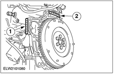
| Pos. | Spare Part No | Name |
| 1 | - | Engine code for 1.4L engine up to model year 2000.25 (Stage II emission standard/Europe excluding Germany) - FXDA |
| - | Engine code for 1.6L engine up to model year 2000.25 (Stage II emission standard/Europe excluding Germany) - FYDA | |
| - | Engine code for 1.4L engine up to model year 2001 (Emission standard Stage III/Europe except Germany): FXDB | |
| - | Engine code for 1.6L engine from model year 2001 (Emission standard Stage III/Europe except Germany): FYDB | |
| - | Engine code for 1.4L engine up to model year 2000.25 (Emission standard D4/Germany) - FXDC | |
| - | Engine code for 1.6L engine up to model year 2000.25 (Emission standard D4/Germany) - FYDC | |
| - | Engine code for 1.4L engine up to model year 2001 (Emission standard D4/Germany): FXDD | |
| - | Engine code for 1.6L engine from model year 2001 (Emission standard D4/Germany): FYDD | |
| - | Engine code for 1.6L engine from model year 2000 (Emission standard ECE-R 15/04): FYDG | |
| 2 | - | Date of manufacture |
Cylinder head cover
NOTE: The cylinder head cover is made of magnesium, the gasket is vulcanized in position and is not replaceable separately. There is no need to install a new cylinder head cover including the gasket every time the cover is removed. Therefore, inspect the gasket first and install a new cylinder head cover only if the gasket is damaged.
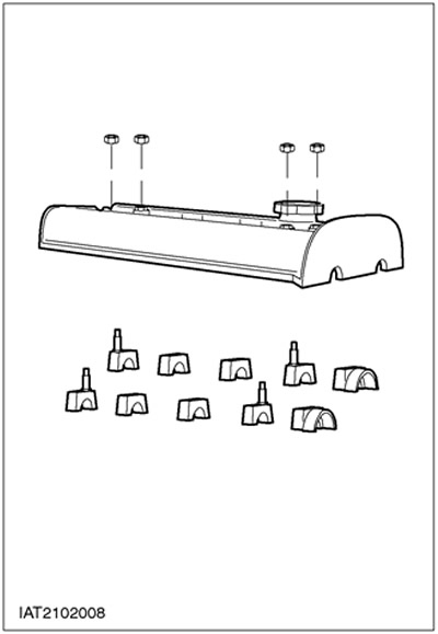
The cylinder head cover is secured to four camshaft bearing caps. Four rubber plugs with torque limiters are used to seal these studs. In the event of a leak, these plugs can be replaced individually. To install, these rubber plugs should be lightly coated with engine oil. Remove excess oil using a clean cloth. When installing a new cylinder head cover, four new plugs should be used. They are supplied with the cylinder head cover.
Camshafts
CAUTION: Before installing the camshafts, lubricate them with engine oil.
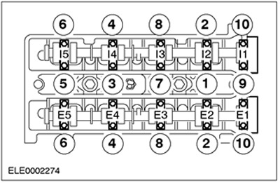
CAUTION: The camshaft bearing caps must be tightened gradually following the specified tightening sequence.
NOTE: The timing belt pulleys are located on the camshafts.
When installing new camshafts, the bearing surfaces should be checked. If damage is detected, the cylinder head and camshaft bearing caps should be replaced as necessary.
The exhaust camshaft has an additional cam for the camshaft position sensor (CMP sensor).
Both camshafts have a forged 21mm hexagon used to turn the shafts.
At the ends of both camshafts there is a groove into which the tool for setting the top dead center is inserted.

The numbering of the bearing caps starts from the side where the timing belt is located and is marked:
- I1 - on the inlet side
- E1 - on the outlet side
The front bearing caps are precisely positioned on the cylinder head by means of guide bushings. These caps are installed with sealant.
Cylinder head
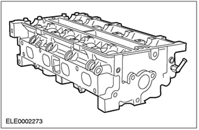
CAUTION: Repair of threads in the cylinder head is not permitted.
CAUTION: Do not rework the cylinder head mating surface.
CAUTION: Machining of valve seats and valve guides is not permitted.
CAUTION: When installing a new SNT sensor, do not damage the pin contact.
NOTE: The cylinder head temperature (CHT) sensor is located near the spark plug of cylinder #3. It measures the cylinder head temperature directly, i.e. does not use coolant temperature. The sensor is deformed during installation and cannot be reused after removal.
NOTE: When installing new valves, they should be lapped (ground) without machining the seats.
The cylinder head is made of aluminum and is precisely positioned on the cylinder block using two guide bushings.
When replacing, the cylinder head is supplied already complete with valves and camshaft bearing caps. The studs should be replaced.
To ensure proper sealing of the cylinder head, the maximum permissible non-flatness of the mating surface of the cylinder block must be equal to 0.05 mm.
Cylinder head gasket
NOTE: The cylinder head gasket can only be properly installed in one position.
The cylinder head gasket is a multi-layer steel gasket that should be replaced every time it is removed.
Cylinder block
CAUTION: To prevent damage to the cylinder head mating surface, always place the cylinder block on a soft surface.
CAUTION: Unlike option 1.6, thread repair is not permitted on option 1.4.
CAUTION: Mechanical treatment of the mating surfaces of the cylinder block is not permitted.
CAUTION: Be careful not to damage the coolant pump impeller when installing or removing.
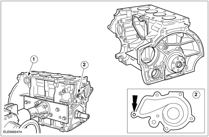
The cylinder block is an aluminum casting obtained by casting into a permanent mold, with cylinder liners made of cast iron.
When replacing, the cylinder block is supplied complete with a crank mechanism and pistons, together with oil gallery plugs and coolant drain plugs.
- 1. For Northern European countries, a heating coil can be inserted into the plug hole.
- 2. In the 1.6L engine block, the threaded hole for the coolant pump can be repaired by installing a threaded sleeve. When doing this, do not exceed the hole depth of 14 mm and the thread length of 11 mm.
Do not reuse the coolant drain plug. Since 09/1999, the cylinder block is no longer equipped with coolant drain plugs.
To ensure proper sealing of the cylinder head, the maximum permissible non-flatness of the mating surface of the cylinder block must be equal to 0.05 mm.
Crank mechanism
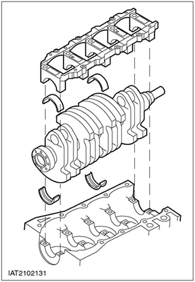
NOTE: Due to the very small clearances in the bearings and bearing shells, the crankshaft components cannot be replaced separately. Measuring the bearing clearances (main bearings and big-end bearings) cannot be done using traditional methods.
Never disassemble the crank mechanism.
The crankshaft is attached to the cylinder block by means of a lower crankcase made of aluminum.
Pistons
CAUTION: Pistons should not be removed.
There are no oversized pistons.
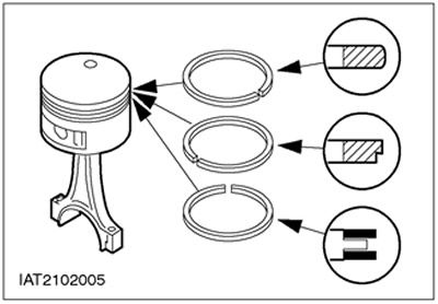
The pistons are made of aluminum alloy and are equipped with three piston rings:
- Rectangular ring (top)
- Step ring (middle)
- Oil scraper ring (lower)
Oil pan
The oil pan is made of aluminum.
When installing, align the oil pan so that it is flush with the cylinder block.
Spacers are not provided.
When tightening, the prescribed tightening sequence and the prescribed tightening torque must be observed.
Engines manufactured up to and including 10.1999
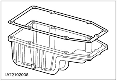
The oil pan gasket should be replaced each time the pan is reinstalled.
Before installing the oil pan in place, apply the prescribed sealant to the cylinder block joints, oil pump flange and crankshaft rear oil seal retainer bearing surface.
Engines manufactured since 11.1999.
The oil pan gasket has been removed and replaced with a "liquid gasket".
Valve mechanism
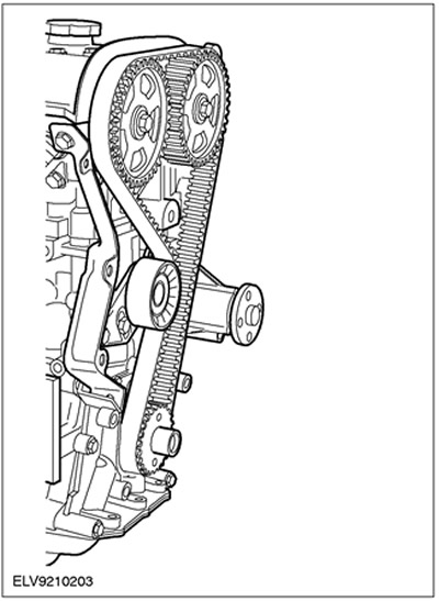
Two overhead camshafts (above the cylinder head) are driven by the crankshaft via the timing belt. They act on the valves via pushrods.
Valve clearances are adjusted using shims that sit on top of the tappets and should be checked every 100,000 km.
Two timing belt tensioners are used:
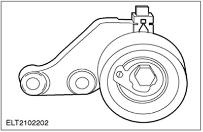
Timing Belt Tensioner with Cam
Timing Belt Tensioner with Groove
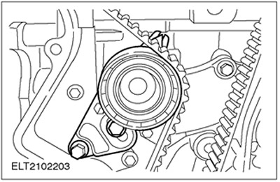
The timing belt should be replaced after 150,000 km or after 10 years.
Crankshaft pulley/vibration damper
CAUTION: After loosening or tightening the crankshaft pulley/damper bolt, check the alignment of the camshafts and crankshaft, i.e. the valve timing.
CAUTION: The crankshaft pulley/damper bolt should only be used once.
CAUTION: Any gaskets that are removed with engine components must be replaced when the components are reinstalled.
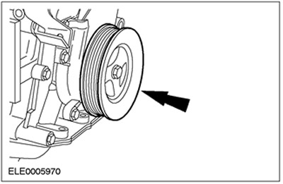
NOTE: If the bolt is not tightened to specification, the crankshaft vibration damper pulley and the crankshaft timing belt pulley that is installed behind it may rotate freely on the crankshaft.
In order to perform adjustment and inspection work, the crankshaft pulley/vibration damper must be correctly installed.