Install the master cylinder in the reverse order of removal. After installation, fill the reservoir with brake fluid and remove air from the hydraulic drive.
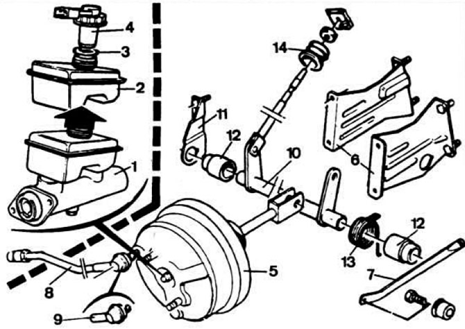 Fig. 6.12. Master cylinder and vacuum booster.
1 - master cylinder; 2 — tank; 3 — tank plug gasket; 4 — plug with emergency liquid level sensor; 5 - vacuum booster; 6 — vacuum booster mounting brackets; 7 - traction; 8 - vacuum hose; 9 - check valve; 10 — intermediate roller; 11 — intermediate shaft mounting bracket; 12 — bushings; 13 - return spring; 14 — rod dust cover.