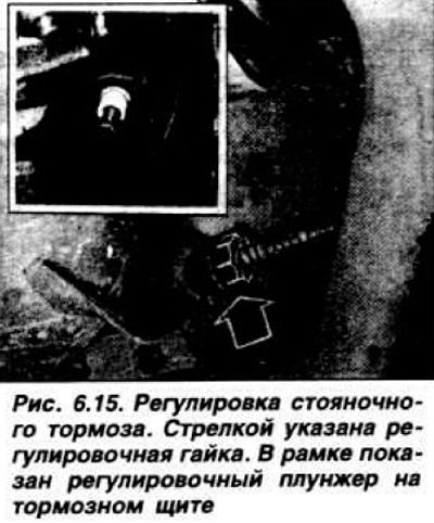
Insert a screwdriver between the adjusting nut and the tip, separate it and, by turning it, completely remove the slack in the cable so that it is possible to turn the adjusting plungers with difficulty. After this, tighten the adjusting nut another 1/4 - 1/2 turn. Tighten lever 1 (Fig. 6.16) to install the adjusting nut on the tip.
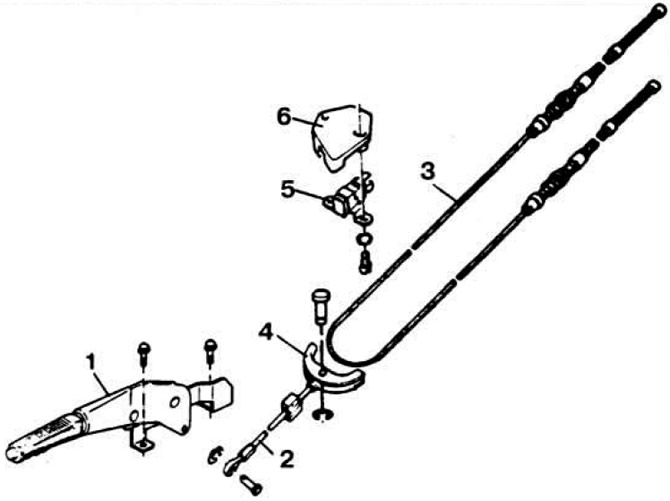 Fig. 6.16. Parking brake.
1 — drive lever; 2 — cable; 3 - equalizing cable; 4 - equalizer; 5 — signal lamp switch; 6 — switch cover.
Check the total free travel of both plungers, which should be within 1.0–2.5 mm.
Since the end of 1983, the parking brake adjustment device has been changed (Fig. 6.17).
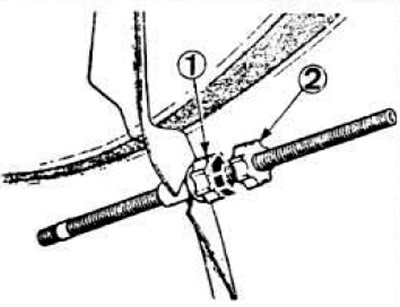 Fig. 6.17. Parking brake adjustment device.
1 - adjusting nut; 2 — lock nut.
Accordingly, the procedure for adjusting the parking brake became as follows. Unscrew the lock nut 2 and the adjusting nut. Do not separate the adjusting nut from the bushing with a screwdriver, since they have an internal thread. Make sure that the brake is not tightened, and the parking brake drive levers rest against the adjusting plungers and do not allow them to move. Loosen the cable and sharply press the brake pedal to select the gap with an automatic device. Do not use a screwdriver to loosen the cable tension, it is enough that the lock nut and adjusting nut are unscrewed. Rotating the nut, bring it to the bracket and o (adjust the total free travel of the plungers within 0.5-2.0 mm. Tighten the lock nut, first by hand until it stops, then tighten it with a wrench by two teeth of the nut. Make sure that the wheels rotate freely.