Water pump
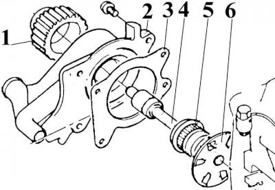
1 – water pump pulley; 2 – body; 3 – gasket; 4 – pump shaft; 5 – seal; 6 – impeller
Oil pump
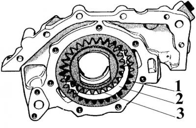
1 – external gear; 2 – dividing partition; 3 – internal gear
Crank mechanism
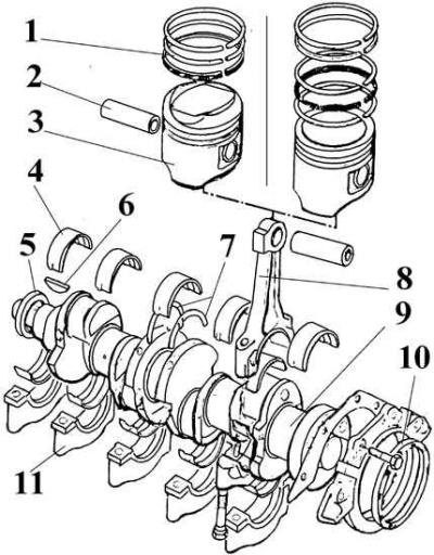
1 – piston rings; 2 – piston pin; 3 – piston; 4 – main bearing; 5 – front sealing ring; 6 – key; 7 – thrust half rings; 8 – connecting rod; 9 – crankshaft; 10 – rear sealing ring; 11 – main bearing cap
Engine cylinder block
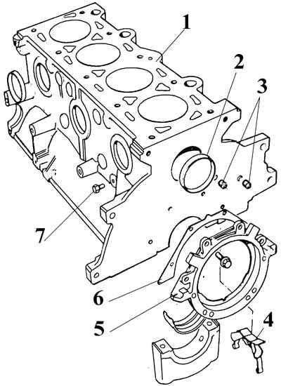
1 – engine cylinder block; 2 – cork; 3 – oil channel plugs; 4 – oil separator; 5 – rear flange of the crankshaft; 6 – gasket; 7 – water drain plug
1. Loosen the lower mounting bolts, unscrew the upper generator tension bolt, tilt the generator toward the engine and remove the drive belt.
2. Unscrew the generator bracket mounting bolts and remove the generator.
3. Remove the heater hose from the water pump.
4. Drain the oil from the engine.
5. Secure the flywheel by the toothed ring, unscrew the mounting bolt and remove the pulley from the crankshaft.
6. Unscrew the 4 timing belt cover mounting bolts and remove it.
7. On engine models manufactured from 2/82, the timing belt cover consists of two parts, each with its own rubber gasket. The lower cover has a mark for setting the first cylinder to TDC. The lower cover can only be removed after the pulley has been removed from the crankshaft.
8. Loosen the timing belt tension roller mounting bolts and use a screwdriver to move the tension roller away from the belt, compress the spring and tighten the bolts.
9. To reinstall the timing belt, mark its direction of movement.
10. Remove the timing belt.
11. Disconnect the ignition distributor cap and remove it together with the high-voltage wires.
12. Unscrew the spark plugs.
13. Remove the crankcase ventilation hose.
14. Unscrew the mounting bolts and remove the carburetor, having first disconnected the fuel and vacuum pipes.
15. Remove the cylinder head cover.
16. Remove the cylinder head.
17. Place the engine horizontally and remove the oil pan.
18. Unscrew the bolts that secure the clutch drive part to the flywheel alternately in a cross pattern, blocking the flywheel ring gear with a screwdriver.
19. Remove the drive part and the clutch disc.
20. Unscrew the flywheel mounting bolts and, being careful, remove the flywheel.
21. Remove the rear engine shield.
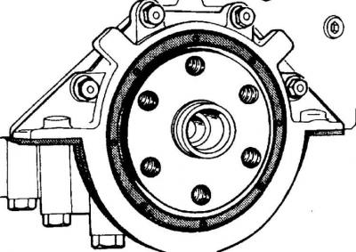
22. Unscrew the bolts and remove the crankshaft rear seal ring cover.
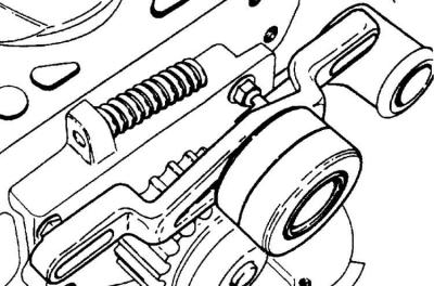
23. Unscrew the timing belt tension roller mounting bolts, remove the tensioner and take out the spring.
24. Remove the water pump (see fig. Water pump).
25. Remove the crankshaft pulley and thrust washer.
26. Unscrew the oil pump mounting bolts and remove it together with the oil intake (see Fig. Oil pump).
27. Remove the oil pressure sensor.
28. Turn the crankshaft to a position where all pistons are at the middle of their stroke.
29. If there is carbon deposits on the top of the cylinder, remove them using a soft scraper.
30. Check the markings on the main bearing caps. The main bearings are marked with numbers from 1 to 5 with arrows pointing toward the timing drive.
31. Check the numbers on the connecting rod caps and connecting rods, as well as their position. Connecting rod #1 is on the timing drive side, and the numbers should be on the oil filter side.
32. Turn the crankshaft by the pulley mounting bolt until the piston of the first cylinder is in the BDC position. Unscrew the connecting rod cover and remove it together with the connecting rod bearing.
33. Remove the piston with the connecting rod upwards (see Fig. Crank mechanism).
34. Remove the remaining pistons in the same manner.
35. Unscrew the main bearing caps and remove the crankshaft.
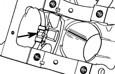
36. Move the spring levers of the engine crankcase ventilation system oil separator down and remove the oil separator (indicated by the arrow).
(The original source of the publication is on the website FORDBOOK)