Special tool
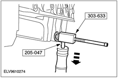
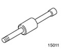 | Hammer with movable head 205-047 (15-011) |
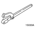 | Universal wrench for holding flanges 205-072 (15030A) |
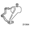 | Support bracket 303-435-04 (21-064) |
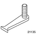 | Flywheel locking tool 303-254 (21-135) |
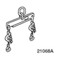 | Engine lift tool 303-122 (21-068A) |
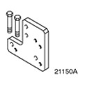 | Base plate 303-435-12 (21-150A) |
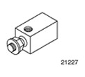 | Oil sump puller 303-633 (21-227) |
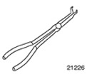 | Pliers for spark plug connectors 303-622 (21-226) |
General equipment:
- wooden blocks
- Fixing clamps
- Lift
1. General remarks:
- Until the assembly stand is connected, the engine remains suspended from the hoist.
- If the engine is installed on an assembly stand and it is required to temporarily detach it from the hoist, the engine must be fixed using the fixing clamps.
- If necessary, cut the clamps and replace them during installation.
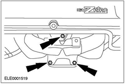
2. Disconnect the catalytic converter bracket.
3. Remove the catalytic converter.
- 1.Remove the heat shield.
- 2. Remove the bolt from the catalytic converter bracket.
4. Remove the catalytic converter (continuation).
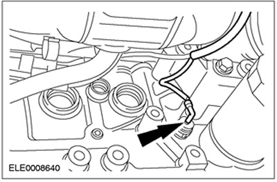
5. Disconnect the oil pressure switch connector.
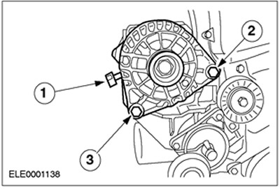
6. Disconnect the generator.
- 1.Disconnect the power cord.
- 2. Remove the bolt.
- 3.Release the bolt.
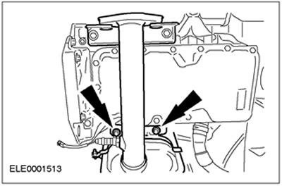
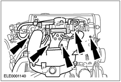
7. Disconnect the intake manifold. Remove seven bolts and two nuts.
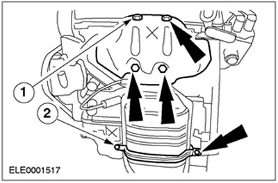
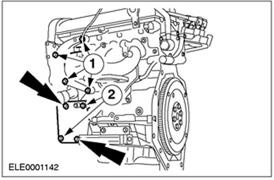
8. Disconnect the additional elements located on the inlet side.
- 1. Generator support bracket.
- 2.Oil filter
- 3. Oil pressure switch
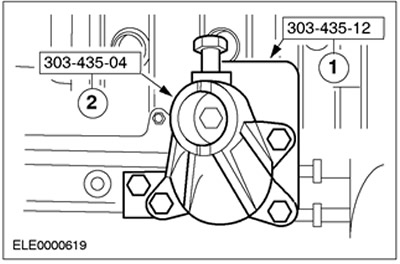
9. Fix the engine on the assembly stand.
- 1.Install the special tool.
- 2.Install the special tool.
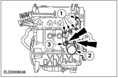
10. Disconnect the additional elements located on the exhaust side.
- 1. Bracket for power steering pump
- 2. Bracket for air conditioning compressor.
11. Disconnect the forced crankcase ventilation system.
12. Disconnect the timing belt cover.
- 1.Water pump pulley
- 2. Intermediate pulley drive belt
- 3.Center Timing Belt Cover/Engine Front Mount Bracket
- 4.Top timing belt cover
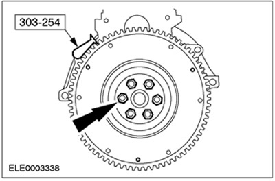
NOTE: Block the flywheel with special tool 303-254.
- 5. Disconnect the pulley/damper from the crankshaft.
- 6.Lower timing belt cover
13.
CAUTION: When disconnecting the spark plug connectors, do not pull on the wire. If necessary, disconnect the ignition wires from the ignition coil to prevent cable twisting. Before disconnecting the spark plug connectors, turn them slightly to loosen the seals.
CAUTION: Disconnect each spark plug connector by applying only a straight line force in the direction of the spark plug axis (for angled spark plug connectors, use special tool 303-622).
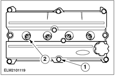
Remove the cylinder head cover.
- Disconnect the spark plug connectors.
- 1.Remove the bolts.
- 2. Remove the spark plugs.
14.
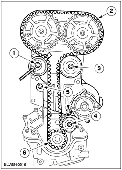
NOTE: Design shown with lower idler pulley (issued until approximately 01.99.).
NOTE: Installation position of crankshaft pulley and thrust washer.
Disconnect the timing belt pulley and water pump.
- 1. Release the timing belt tensioner by turning it counterclockwise and disconnect.
- 2.Remove the timing belt.
- 3.Disconnect the upper intermediate pulley.
- 4.Disconnect the lower intermediate pulley.
- 5.Disconnect the water pump.
- 6. Remove the crankshaft pulley and thrust washer.
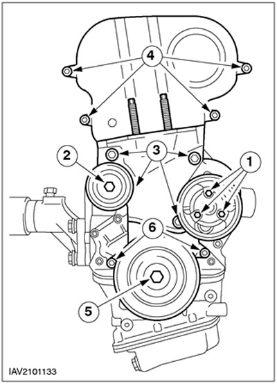
15.
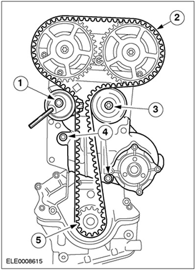
NOTE: Design shown without lower idler pulley (released starting around 01.99.).
NOTE: Installation position of crankshaft pulley and thrust washer.
Disconnect the timing belt pulley and water pump.
- 1. Release the timing belt tensioner by turning it counterclockwise and disconnect.
- 2.Remove the timing belt.
- 3.Remove the intermediate pulley.
- 4.Disconnect the water pump.
- 5.Remove the crankshaft pulley and thrust washer.
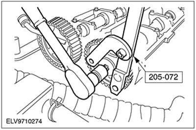
16. Remove pulleys from camshafts. Use a special tool to prevent the pulleys from turning.
17.
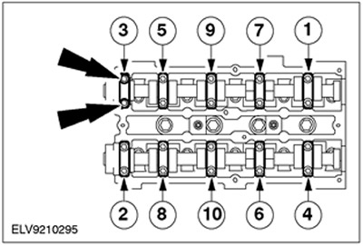
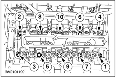
NOTE: Loosen each bolt, working evenly, in several steps, in the sequence shown, releasing two turns per step, and remove the bolts.
Disconnect the camshaft bearing caps.
- Remove oil seals.
- Remove camshafts.
- Remove the valve lifters and set them aside one by one.
18.
CAUTION: Mark the bolts to be reused by punching one or two dots on them. Bolts can be reused twice. Discard bolts if necessary.
CAUTION: Allow the cylinder head to cool to room temperature before proceeding with the following steps.
NOTE: Follow the release sequence.
Turn out bolts of a head of cylinders.
19. Raise the cylinder head. Attach a hoist to the engine lifting lugs, lift and remove the cylinder head and place it on a clean piece of wood.
20. Disconnect the clutch pressure and driven discs.
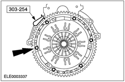
21. Remove the flywheel. Disconnect the special tool.
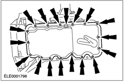
22. Turn out a drain stopper and bolts of an oil case.
23.
CAUTION: To avoid damaging the sealing surfaces, use only a tool specifically designed for removing the oil pan to remove it. Do not use a chisel or screwdriver to remove.
Remove the oil pan. Connect the special tool, screw the locknut all the way into the oil pan, and disengage the oil pan from the bottom section of the crankcase with a few taps.
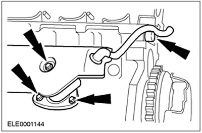
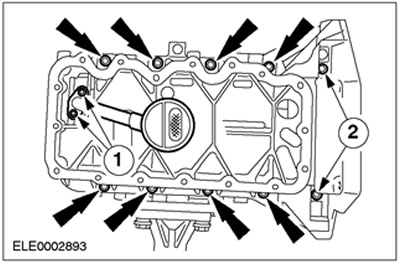
24. Disconnect the oil inlet line and lower crankcase section.
- 1. Oil intake pipe bolts
- 2. Bolts of the lower section of the crankcase
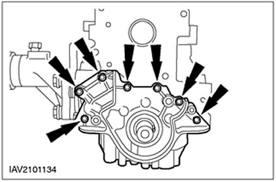
25. Remove the oil pump.
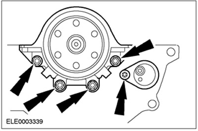
26. Disconnect the crankshaft rear oil seal retainer and crankshaft position sensor (TFR) along with the bracket.
27.
NOTE: Set all items aside one by one.
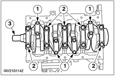
Remove the crankshaft and pistons.
- 1. Disconnect the bearing caps of the lower heads of the connecting rods.
- 2. Disconnect the main bearing caps.
- 3. Remove the crankshaft and remove the pistons and connecting rods.
Visitor comments