Special tool
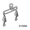 | Engine Lifting Tool 303-122 (21068A) |
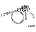 | Radiator Hose Clamp Remover and Installer 303-397 (24-003) |
General equipment:
- Assembly table
- Fixing clamp
- Engine lifting crane
- Wooden blocks
| Name | Specification |
| High temperature grease | ESD-M1C220-A |
All cars
NOTE: If necessary, use special tool 303-397 to install and remove coolant hoses and vent hoses.
1. Using a clamp and wooden blocks, secure the gearbox to the drive axle block on the assembly stand.
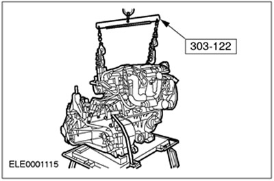
2. Using a suitable crane to lift the engine, align the engine position relative to the transaxle.
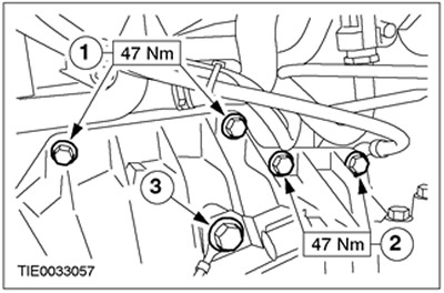
3. Install the right transmission mounting bolts in the block with the drive axle.
- 1.Flange bolts
- 2.Starter bolts
- 3.Connect the ground cable.
4. Install the lower transmission mounting bolts in the block with the drive axle.
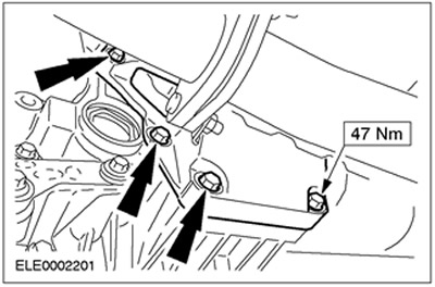
5. Install the left transmission mounting bolts in the block with the drive axle.
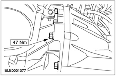
6. Install the starter and tighten the flange bolt.
- 1.Starter bolt
- 2.Flange bolt
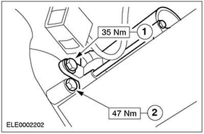
7. Raise the vehicle. Refer to Section 100-02 for additional information.
8. Install the engine assembly with the gearbox in the block with the drive axle, secured on the assembly stand, under the car. Carefully lower the car.
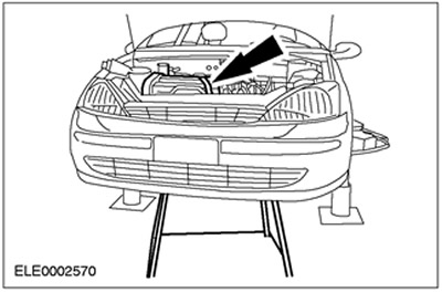
9.
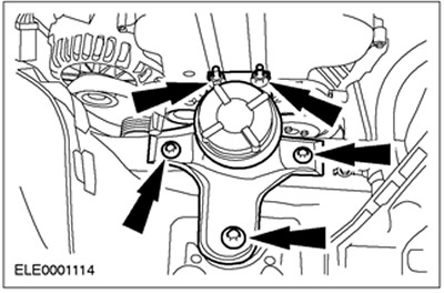
NOTE: Do not fully tighten the bolts and nuts at this stage.
Install the front engine mount.
10.
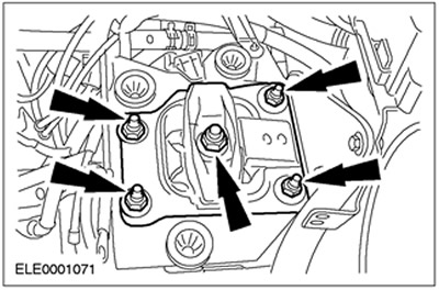
NOTE: Do not fully tighten the bolts and nuts at this stage.
Install the rear engine mount.
11.
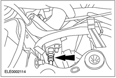
CAUTION: If brake fluid comes into contact with the paintwork, the affected area must be immediately washed with cold water.
Connect the clutch slave cylinder supply line.
12. Remove the retaining clamp from the gearbox in the block with the drive axle.
13. Raise the vehicle. Refer to Section 100-02 for additional information. Remove the assembly stand.
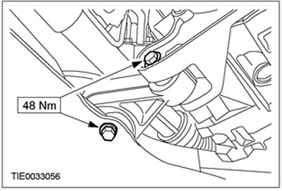
14. Install the engine support cushion.
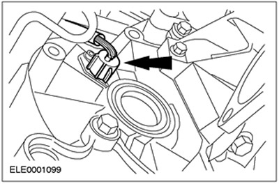
15. Connect the vehicle speed sensor (VSS) connector.
16.
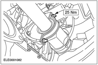
CAUTION: The inner hinge must not be deflected at an angle exceeding 18 degrees. The outer hinge must not be deflected at an angle exceeding 45 degrees.
NOTE: Use new nuts and a new intermediate bearing cap.
Install the right front axle shaft and intermediate shaft.
17.
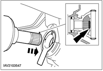
NOTE: Make sure the snap ring is installed correctly.
Install the left front axle shaft.
18.
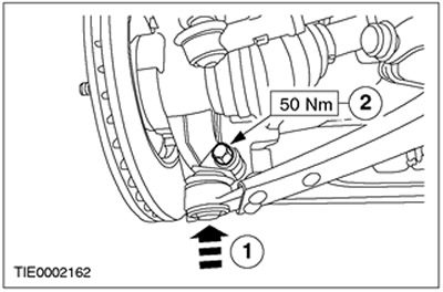
CAUTION: Make sure the heat shield is installed to prevent damage to the ball joint.
Connect the lower control arm ball joint to the steering knuckle (on both sides).
- 1.Install the lower arm ball joint.
- 2.Install the bolt.
19. Install the flexible exhaust system insert.
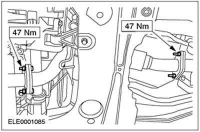
20. Install the front wheel and tire assemblies. Refer to Section 204-04 for additional information.
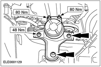
21. Tighten the rear engine mount nuts and bolts.
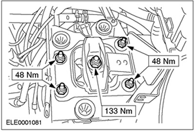
22. Tighten the rear engine mount mounting nuts.
23. Raise the vehicle. Refer to Section 100-02 for additional information.
24. Install the lower power steering pump mounting bolts.
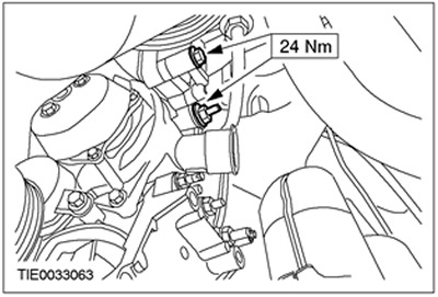
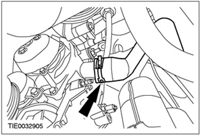
25. Connect the coolant pump hose.
Cars with air conditioning system
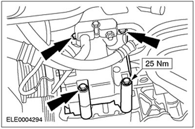
26. Connect the air conditioning compressor to the engine.
All cars
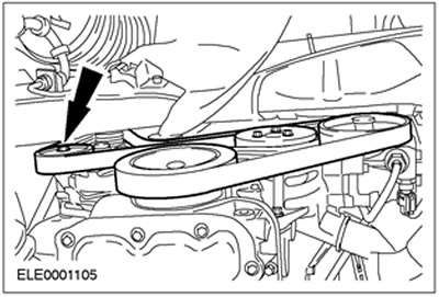
27. Install the accessory drive belt. (vehicle without air conditioning system shown) Turn the belt tensioner clockwise.
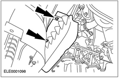
28. Install the accessory drive belt cover.
29. Connect the shift and selector cables to the transaxle. Turn the support sleeve clockwise on the bracket.
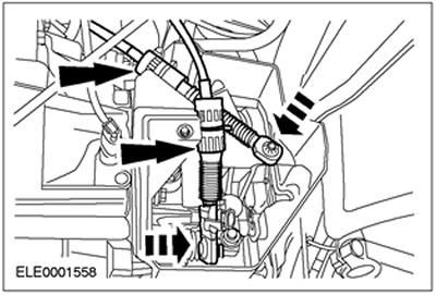
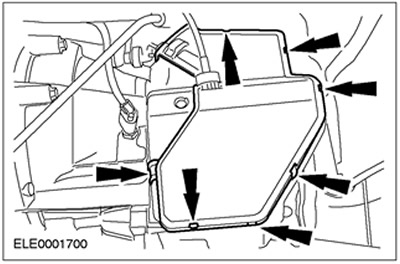
30. Close the shift and selector cable cover.
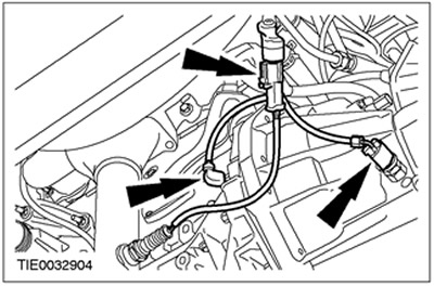
31. Connect the reverse light switch, crankshaft position (CKP) sensor and heated oxygen sensor (HO2S) connectors. Connect the wiring harness to the engine.
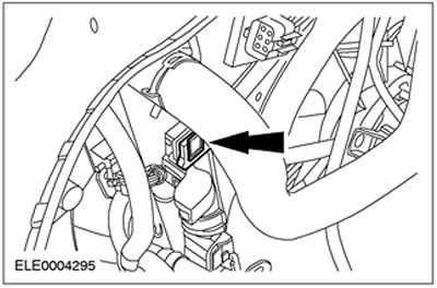
32. Install the air deflector and radiator fan. Install the air deflector and secure it to the top on both sides (left side shown).
33. Lower the car.
34. Connect the coolant hoses to the engine.
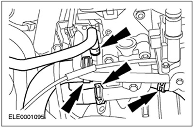
35. Connect the fuel lines and ground wire to the manifold.
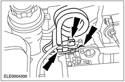
36. Connect the brake booster vacuum hose.
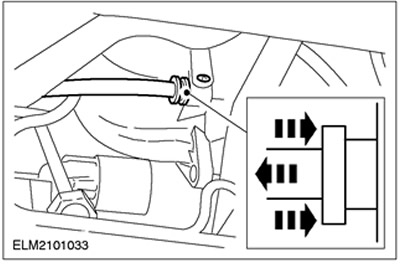
37. Connect the vacuum hoses to the throttle body.
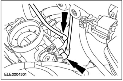
38. Connect the engine wiring harness plug connector.
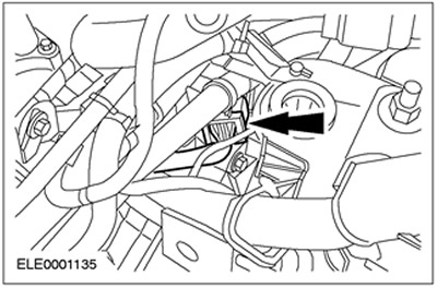
39. Connect the generator plug.

40.
CAUTION: If brake fluid comes into contact with the paintwork, rinse the affected area with cold water.
Connect the clutch slave cylinder feed line. Connect the spring clamp.
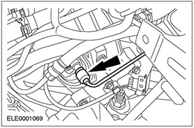
41. Connect the radiator fan connector. Install new clamps.
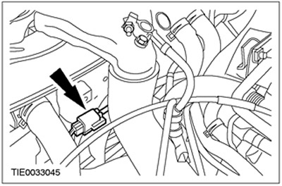
42. Connect the powertrain control module (PCM) connector. Install new clamps.
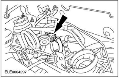
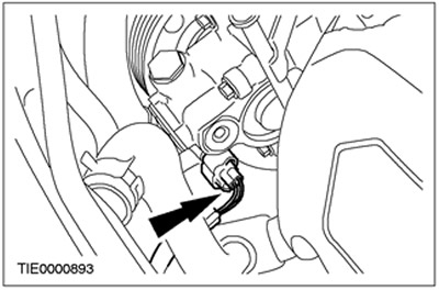
43. Connect the power steering pressure (PSP) switch connector.
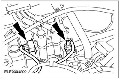
44. Connect the plug connectors of the EI coil and the plug connectors of the radio interference suppression filter.
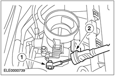
45. Connect the accelerator cable to the throttle body.
- 1. Fix the cable in the required position.
- 2. Fix the plastic clamp.
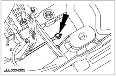
46. Connect the headlight ground wire.
47. Install the air filter housing.
- 1. Connect the mass air flow (MAF) sensor connector.
- 2.Connect the breather line to the air filter.
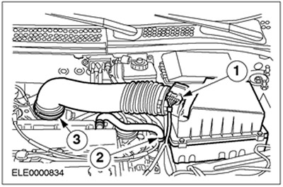
- 3.Connect the air cleaner outlet pipe to the throttle body.
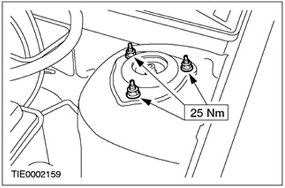
48. Tighten the nuts securing the upper support of the suspension strut assembly with the spring (on both sides).
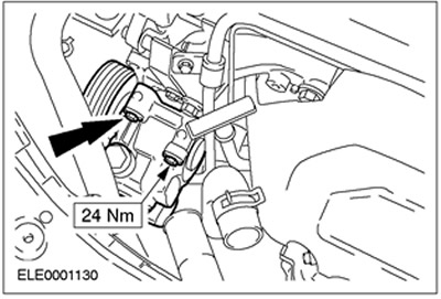
49. Install the upper power steering pump mounting bolts.
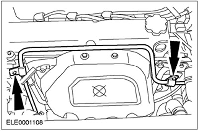
50. Connect the power steering line to the engine.
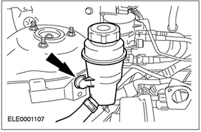
51. Secure the power steering fluid reservoir to the wheel arch.
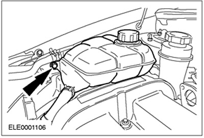
52. Secure the expansion tank of the cooling system to the wheel arch.
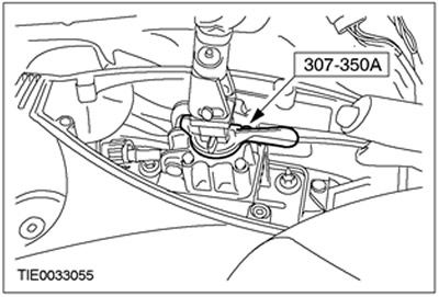
53. Remove the special tool.
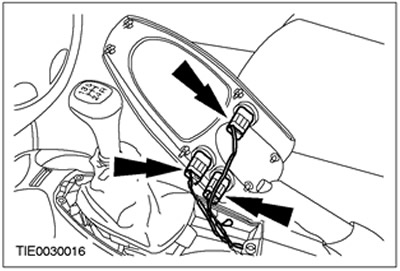
54. Connect the traction control and heated seat (if equipped) connectors.
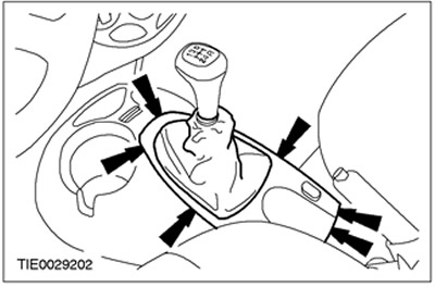
55. Connect the gear shift lever trim to the floor console.
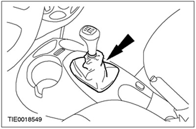
56. Attach the gear shift boot to the floor console.
57. Install the battery tray. Refer to Section 414-01 for additional information.
58. Fill with coolant. Refer to Section 303-03 for additional information.
59. Check the transaxle fluid level and correct if necessary. Refer to Section 308-03A / 308-03B / 308-03C for additional information.
60. Bleed the clutch hydraulic system. For additional information, refer to Section 308-03A / 308-03B / 308-03C.
(The original article is available on the website: FORDBOOK.RU)