Special tool
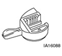 | Neutral Switch Alignment Tool 307-350 (16-088) |
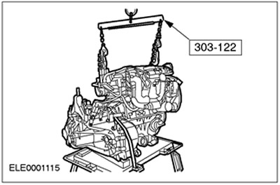
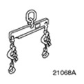 | Engine lift tool 303-122 (21068A) |
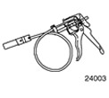 | Radiator hose clamp remover and installer 303-397 (24-003) |
General equipment:
- assembly table
- Fixing clamp
- Repair shop crane
- wooden blocks
| Name | Specification |
| clamps | |
| High temperature grease | ESD-M1C220-A |
| transmission fluid | ESDM-2C186-A |
All cars
1. Replace self-locking nuts and retaining ring.
- If necessary, use special tool 303-397 when installing the coolant and vent hoses.
- 2. Preparatory operations
- Using the fixing clamp for fastening, install the gearbox on the assembly stand.
- Hitch the engine to the repair zone crane, bring it into the required position in relation to the gearbox and support it using wooden blocks.
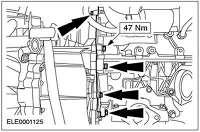
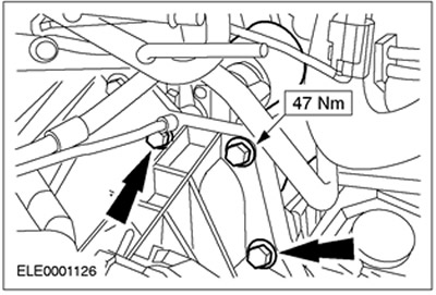
3. Tighten the flange bolts.
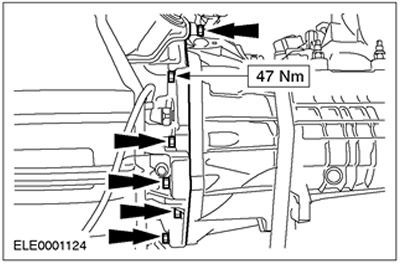
4. Tighten the flange bolts. Unhook the engine from the crane.
5. Install starter and ground wire.
6. Raise the vehicle. See Section 100-02 for more information.
7. Install the engine assembly with the gearbox, fixed on the assembly stand, under the car. Lower the car carefully.
8.
NOTE: Hand tighten/tighten bolts and nuts.
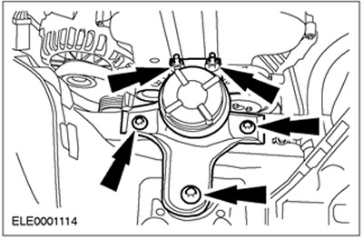
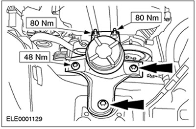
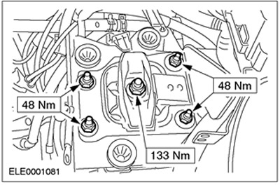
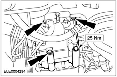
Install the front engine mount.
9.
NOTE: Hand tighten the nuts.
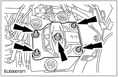
Install the rear engine mount.
10. Remove a fixing collar from a transmission.
11. Raise the car. See Section 100-02 for more information. Remove the assembly stand.
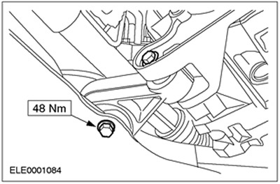
12. Install the engine roll limiter.
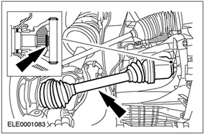
13.
CAUTION: The inner hinge must not be tilted more than 18 degrees and the outer hinge must not be tilted more than 45 degrees.
NOTE: Use new bolts and a new intermediate bearing cap.
Connect the right forward half shaft with an intermediate shaft.
14.
CAUTION: The inner hinge must not be tilted more than 18 degrees and the outer hinge must not be tilted more than 45 degrees.
NOTE: Use a new retaining ring.
NOTE: Lock the circlip in place.
Connect the left front axle shaft.
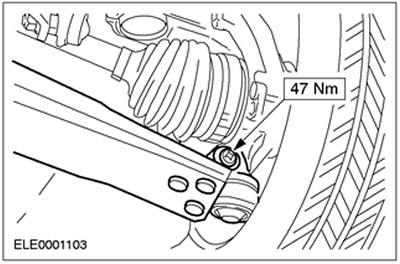
15. Connect both suspension arms (right side shown).
16. Install both front wheels. See Section 204-04 for more information.
17. Install flexible exhaust pipe.
18. Lower the car.
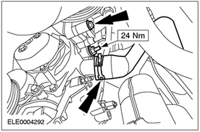
19. Tighten the nuts/bolts of the front engine mount.
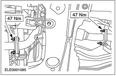
20.
NOTE: Tightening sequence.
Install the rear engine mount nuts, but do not tighten them.
- Tighten the M14 nut first.
- Then tighten the M10 nuts evenly, working in a crosswise manner.
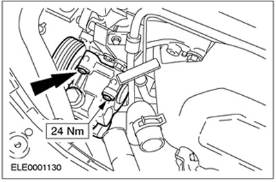
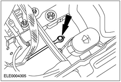
21. Install the power steering pump and screw in the top bolts.
22. Connect an arm for the pipeline of a high pressure of the amplifier of a steering.
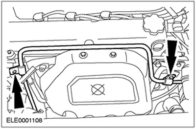
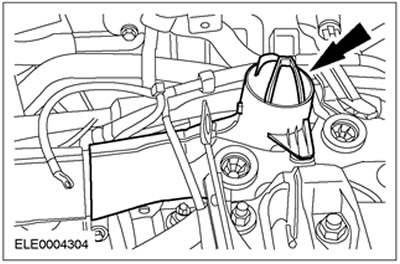
23. Connect the PAS tank.
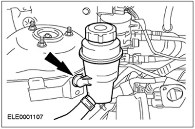
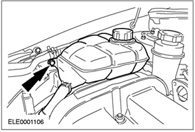
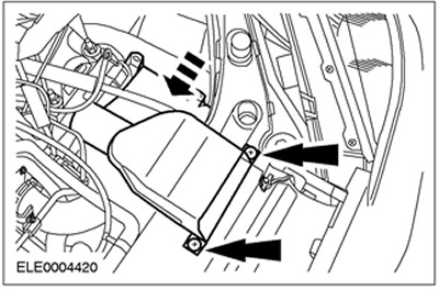
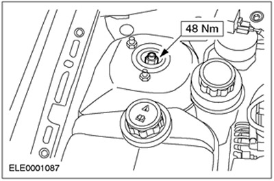
24. Install the expansion tank of the cooling system.
25. Raise the car. See Section 100-02 for more information.
26. Install the two lower power steering pump bolts and connect the coolant hose.
Vehicles with air conditioning
27. Install the air conditioning compressor.
All cars
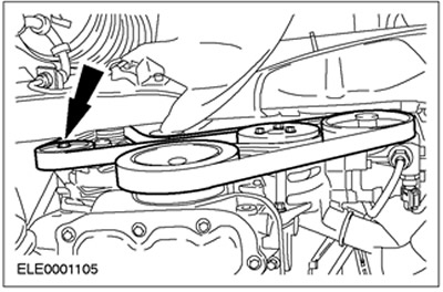
28. Put on and tension the drive belt. Vehicle shown without air conditioning. Turn the belt tensioner clockwise.
29. Install drive belt cover
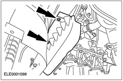
30. Install the air deflector and radiator fan. Align the position of the air baffle and fix it from above on both sides (left side shown).
31. Lower the car.
32. Connect coolant hoses.
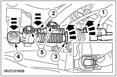
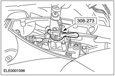
33.
NOTE: The adjustment mechanism must be unlocked.
Connect and adjust the shift lever and select lever cables in the transmission.
- 1. Loosen the support bushings by turning them counterclockwise and install the gear selector cable into the bracket.
- 2. Connect the shift cable to the selector lever.
- 3. Loosen the support bushings by turning them counterclockwise and install the shift cable into the bracket.
- 4. Connect the shift cable to the shift lever.
- 5.Lock the adjustment mechanism by crimping the clip.
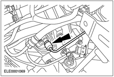
34. Connect fuel lines. Connect the ground wire.
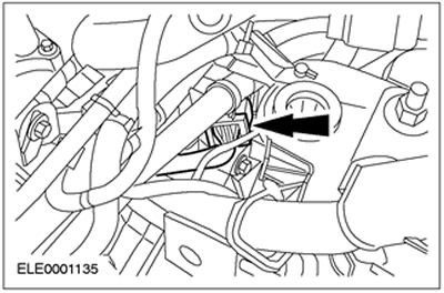
35. Connect a vacuum hose of the vacuum amplifier of brakes.
36. Connect vacuum hoses.
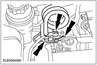
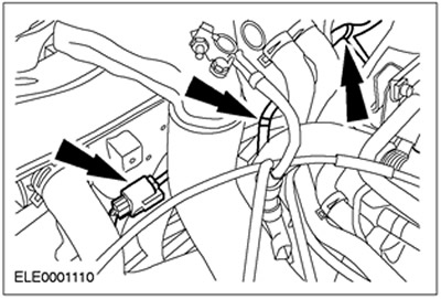
37. Dock the plug connectors of the reversing lamp switch and the TFR. Fix the wiring harness in the required position.
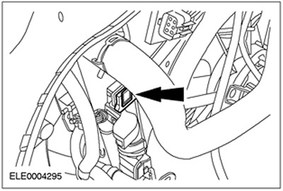
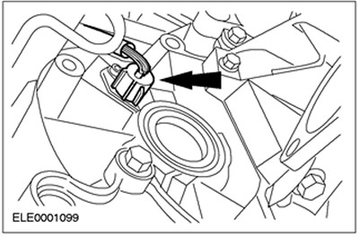
38. Dock the engine wiring harness connector.
39. Connect the VSS male connector.
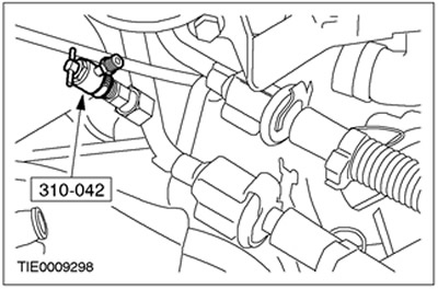
40.
CAUTION: Brake fluid leakage. Observe precautions for handling brake fluid. See Section 206-00 for more information.
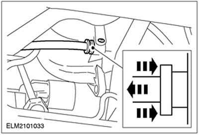
Connect the high pressure line to the clutch slave cylinder. Install the spring clip.
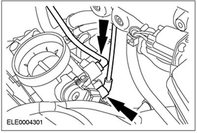
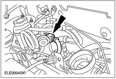
41. Dock the heated oxygen sensor connector (HO2S) and power steering pump pressure switch connector.
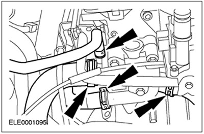
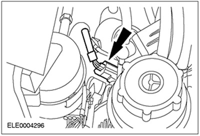
42. Connect the radiator fan connector. Install clamps.
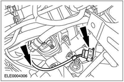
43. Connect the PCM connector.
44. Connect the alternator connector.
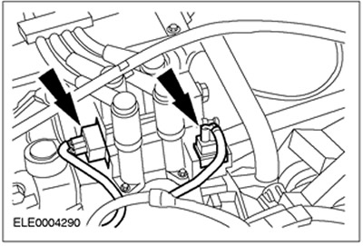
45. Connect the connectors of the EI coil and the RFI filter.
46. Install the accelerator cable.
- 1. Attach the accelerator cable.
- 2.Fix the plastic clip.

47.
NOTE: The resonator is connected with a tight fit.
Install the air filter intake pipe with the resonator.
48. Install the inlet pipeline.
49. Connect the ground cable.
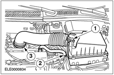
50. Install the air filter housing.
- Insert the air filter housing into the rubber bushings.
- 1.Connect the MAF sensor connector (MAF sensor).
- 2. Connect the crankcase ventilation hose.
- 3.Connect the inlet hose.
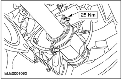
51.
NOTE: Lock against rotation with the Allen key.
Tighten the nuts of the right and left suspension struts.
- • Finger tighten with a ring wrench.
- • Use a torque wrench to tighten to the prescribed torque.
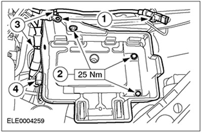
52. Install the battery tray.
- 1.Connect the ground wire and the positive wire.
- 2. Screw in the bolts.
- 3. Fix the wiring harness in the required position.
- 4.Connect and secure the plug connector.
53. Install the battery.
54. Disconnect the special tool. Fix covers.
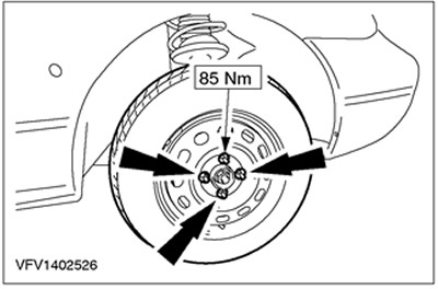
55. Tighten wheel nuts.
56. Standard final operations:
- Fill with coolant. See Section 303-03 for more information.
- Bleed the air from the hydraulic clutch. See Section 308-00 for more information.
- Enter the radio key code.
- Reprogram preset radios.
- Carry out a road test to give PCM a chance to collect data.
Visitor comments