Special tool
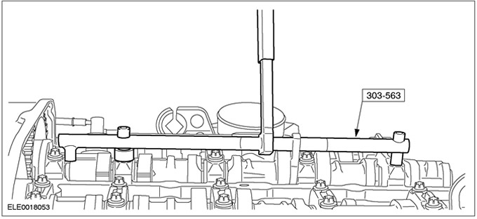
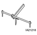 | Valve clearance spring compressor tool 303-563 (21-218) |
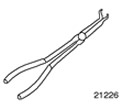 | Spark Plug Pliers 303-622 (21-226) |
General equipment:
- Set of feeler gauges
- Micrometer
- Bushing (8 x 12 mm) or suitable washers
| Name | Specification |
| Clamps | |
| Silicone grease for spark plug connector seals | A960-M1C171-AA |
Adjustment
1.
CAUTION: To adjust the valve clearance, replace the adjusting shims.
Disconnect the ground cable from the battery. For additional information, refer to Section 414-01.
2.
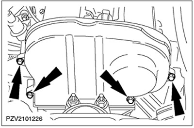
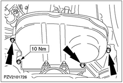
NOTE: Do not remove the upper timing belt cover.
Loosen the bolts in the upper timing belt cover.
3.
CAUTION: When disconnecting the spark plug connector, do not pull on the wire. If necessary, disconnect the ignition wires from the ignition coil to prevent twisting. Before disconnecting the spark plug connector, twist it slightly to release the seal.
CAUTION: When disconnecting the spark plug connector, keep it aligned with the spark plug.
NOTE: Release sequence: from outside to inside, working in a criss-cross pattern.
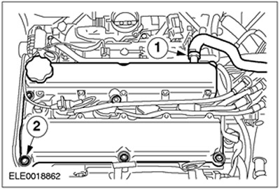
Remove the cylinder head cover.
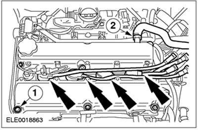
- Disconnect the spark plug connectors.
- 1. Disconnect the crankcase ventilation hose.
- 2. Unscrew ten bolts.
4.
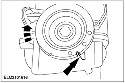
CAUTION: Crank the engine only through the crankshaft and in its normal direction of rotation.
Set the engine to top dead center position for cylinder #1.
5.
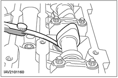
NOTE: Note each cylinder number and measured valve clearance.
Measure the valve clearance using a feeler gauge.
- Permissible valve clearance: Inlet valve (0.11 - 0.18 mm)
- Permissible valve clearance: Exhaust valve (0.27 - 0.34 mm)
- Rotate the crankshaft further in successive stages of 180 degrees each time and check the valve clearances in the remaining cylinders. In this case, the measurement sequence corresponds to the firing order: 1-3-4-2
6.
NOTE: Perform the following steps only if the valve clearance needs to be adjusted.
Connect the special tool.
7.
NOTE: Aim for valve clearances in the middle of the acceptable range (intake valves - 0.15 mm; exhaust valves - 0.30 mm)
NOTE: The gasket number indicates the thickness of the gasket. Example: 222 = 2.22 mm.
Determine the required gasket thickness.
- Remove the shim from the tappet and read the thickness from the number stamped on the back (if it is not clear, measure the thickness of the shim using a micrometer).
- Determine the required shim thickness and insert the adjusting shim.
- Inlet valves: thickness of the gasket to be installed = thickness of the existing gasket + measured valve clearance - 0.15 mm.
- Exhaust valves: thickness of the gasket to be installed = thickness of the existing gasket + measured valve clearance - 0.30 mm.
8. Replace the adjusting linings.
9. Remove the special tool.
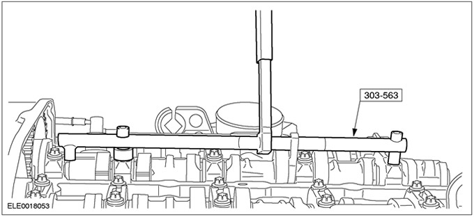
10. After completing the adjustment, recheck the valve clearances.
11.
CAUTION: To avoid damaging the spark plug connector seal, use a blunt object (such as a plastic zip tie) to apply silicone grease.
CAUTION: When mating the spark plug connector, keep it in line with the spark plug.
NOTE: Coat the inside of the spark plug connector with silicone grease to a depth of (5-10) mm.
Install the cylinder head cover.
- 1.Install the ten bolts and tighten them in two stages.
- Stage 1: 2 Nm
- Stage 2: 7 Nm
- 2.Install the crankcase ventilation hose.
- Connect the spark plug connectors until they snap into place.
12.
NOTE: Check that the gasket on the upper timing belt cover is installed correctly and adjust it if necessary.
Install the upper timing belt cover.
13. Connect the ground cable to the battery. For additional information, refer to Section 414-01.
14. Check the levels of working fluids and adjust them if necessary.
15. Check that the vacuum hoses, cables and wires are routed correctly and secure them in the required position using clamps.